The meter has the function of ACV/DCV automatic Identification (voltage ~ 0.5V). If you want to measure
voltage less than 0.5V, press the SELECT button to toggle the AC and DC voltage to lock the measurement
mode; After pressing the SELECT button, the meter no longer has the function of ACV /DCV automatic
Identification, unless you turn the range switch or restart the meter
Note:
* Do not measure voltage above 600Vrms. Although it is possible to measure higher voltage, it may damage the
meter and hurt the user! If the LCD displays “OL”, ii indicates that the voltage is over range. The input impedance of
the meter is 10MΩ. This load effect may cause measurement error when measuring high impedance circuits. If the
measured impedance is ≤10kΩ, the error can be ignored (~0.1%).
* Be cautious to avoid electric shock when measuring high voltage.
* Test known voltage before use to confirm if the meter functions properly!
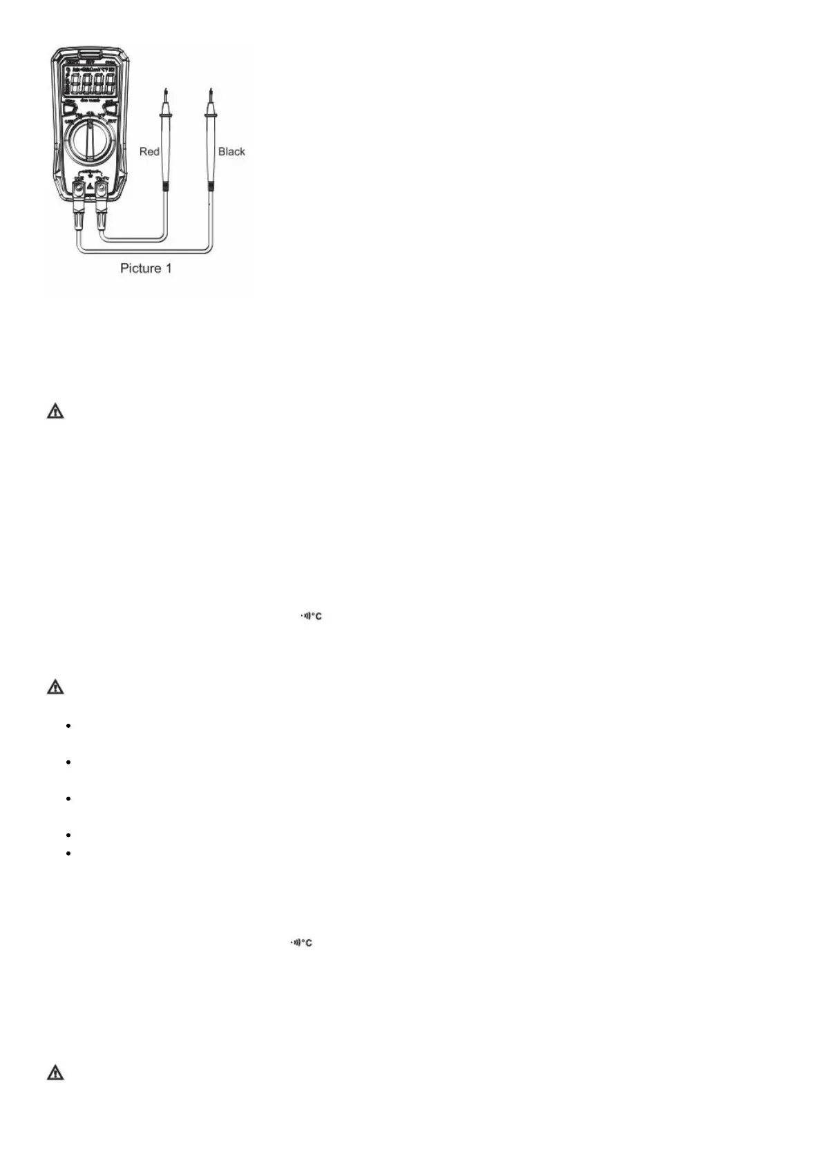
4.2 Resistance Measurement (Picture 1)
1. Tum the range switch to the resistance measurement position;
2. Insert the red test lead into the “v Ω • jack, black into the “COM” jack, and make the probes in contact with
both ends of the measured resistance (parallel connection to the resistance);
3. Read the test results on the display.
Note:
Before measuring the online resistance, switch off the power supply of the circuit, and fully discharge all
capacitors to avoid damage to the meter and user.
If the resistance is not less than 0.50 when the test leads are shorted, please check if the test leads are loose or
abnormal.
If the measured resistor is open or the resistance exceeds the maximum range, the “OL” symbol will appear on
the display.
Do not input voltage higher than DC 60V or AC 30V.
Measured value = measured display value – short circuit value of the test leads
4.3 Continuity Measurement (Picture 1)
1) Turn the range switch to the continuity measurement position;
2) Insert the red test lead into the ” VΩ ” jack, black into the “COM” jack, and make the probes in contact with the
two test points;
3) Measured resistance ≤30Ω: The indicator lights up green accompanied by continuous beeps, indicating that the
on-resistance is small, and the LCD displays the corresponding resistance value.
Measured resistance within 31Ω-420Ω: The indicator lights up red accompanied by no beep, indicating that the on-
resistance is large, and the LCD displays the corresponding resistance value. Measured resistance >420Ω: The
indicator and buzzer have no response, indicating that the circuit is open. The LCD displays “OL”.
Note:
• Before measuring the continuity online, switch off the power supply of the circuit, and fully discharge all capacitors
to avoid damage to the meter and user.
 Loading...