UT219PV User Manual
17 / 27
5 Hz~10 Hz: ≥10 A
10 Hz~100 Hz: ≥5 A
100 Hz~999.9Hz: ≥10 A
● The error specified by the flex current sensor is the intrinsic error of UT219PV.
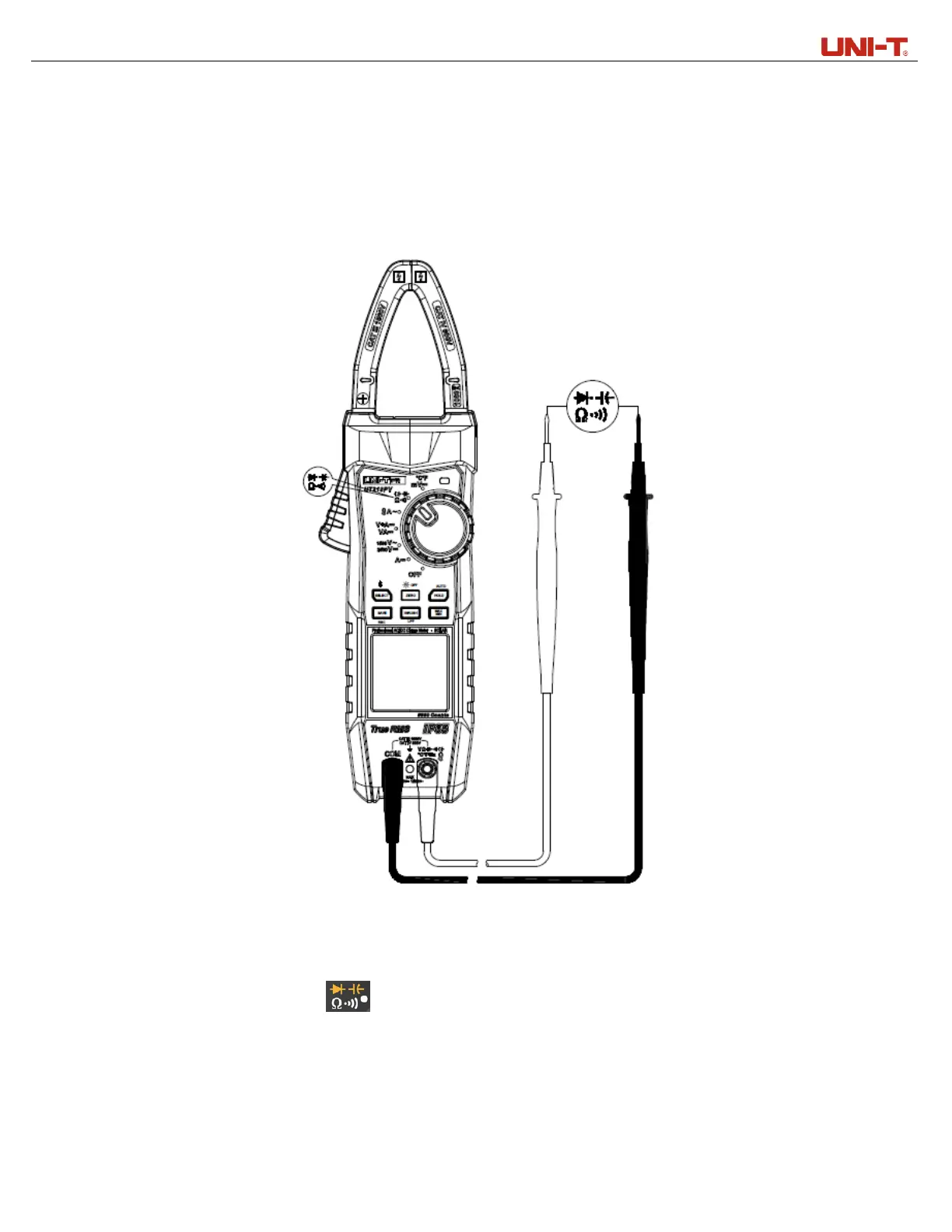
5. Resistance measurement (Figure 10)
Figure 10
1) Connect the red test lead to “V” terminal and black to “COM”.
2) Set the rotary switch to “ ”, short press the SELECT button to switch to the resistance
measurement position, then connect (in parallel) the test leads with both ends of the resistor to be
measured.
3) Read the measurement result from the LCD.
 Loading...