UT593/595 OPERATING MANUAL UT593/595 OPERATING MANUAL
Notice:
Prior to test, ensure that the circuit to be test is not live. Do not measure the insulation of live
equipment or live circuit.
Prior to test, when voltage between two measuring terminals is more than 30V, the instrument will
automatically display the voltage between two terminals. At the same time, the buzzer gives an
alarm. In this case, the measuring key TEST is disenabled.
If the battery cover is opened, do not conduct measurement.
Notice:
Do not short-circuit two test pens under high voltage output state and do not measure the
insulation resistance after high voltage output.
After ensuring that the object to be tested is not live, correctly connect the object to be tested to
the instrument according to connection diagram; and then make the rotary switch point to
Insulation and select the proper test voltage; then press the TEST key to start insulation
resistance measurement.
Selection and operation of function keys F1-F4 is shown below:
F1 F2
F3
F4
Buzzer and backlight
Test lock Not used
Not used
Instructions on key operation:
Press and hold F1 for about 2 seconds to open and close the backlight; press and release F1 to
open and close 20 Ù comparison function; when the measured insulation resistance value is
lower than 20 Ù, the buzzer will give an alarm.
F2 is used to open and close the measuring lock function. When long-time measurement is
needed, press F2 to start TEST lock measurement function; at the same time, the LCD displays
the symbol of lock. In this case, you only need to press and release the Test key to start long-
time measurement.
Press the test key again to stop measurement. If you want to close the measuring lock function,
press the F2 again or make the rotary switch point to other functions.
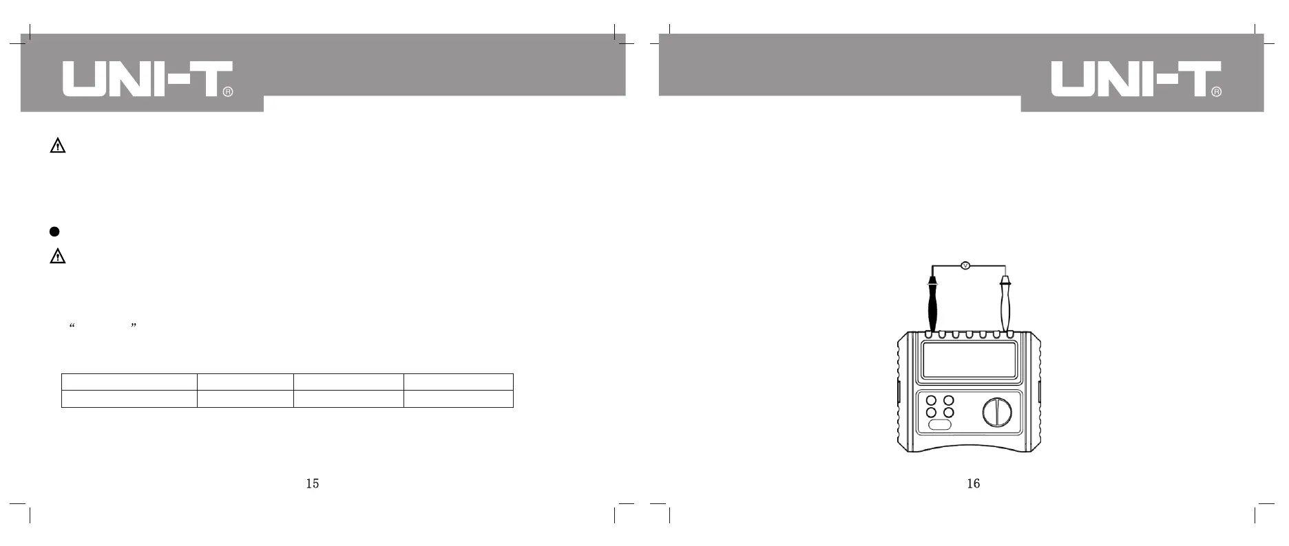
IX. VOLTAGE/FREQUENCY MEASUREMENT
(SEE FIG. 5 FOR CONNECTION DIAGRAM)
(Fig. 5)