UT593/595 OPERATING MANUAL UT593/595 OPERATING MANUAL
Selection and operation of function keys F1-F4 is shown below:
F1 F2
F3
F4
Buzzer and backlight
Not used
Not usedNot used
Instructions on key operation: Press and hold F1 for about 2 seconds to open and close the
backlight; no function is available for other F2, F3, F4 and TEST.
* Do not input voltage higher than 440V or 44Vrms. It is possible to display higher voltage, but it
has the risk to damage the instrument.
* In measuring of higher voltage, special attention shall be given to avoiding electric shock.
* After all measuring operations are completed, disconnect the test line from the tested circuit and
remove the test line from the instrument input end.
* If the battery cover is opened, do not conduct measurement.
XI. MEASUREMENT OF FAULT LOOP CIRCUIT IMPEDANCE/ FAULT
EXPECTED SHORT-CIRCUIT CURRENT (SEE FIG. 7 AND 8 FOR
CONNECTION DIAGRAM)
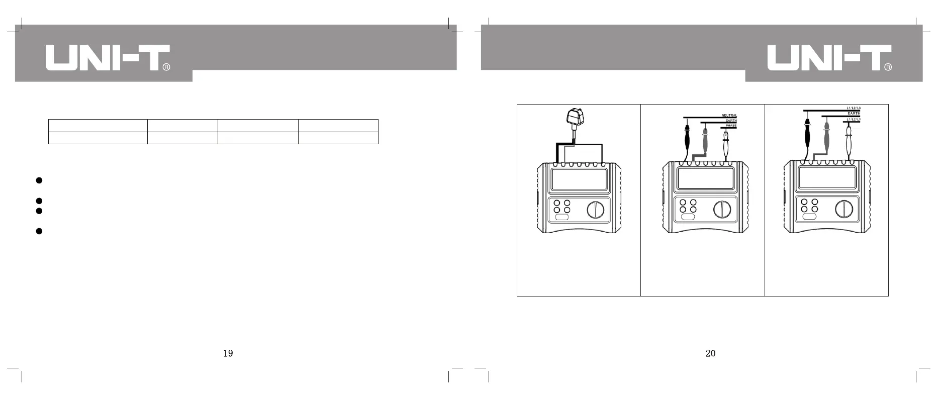
1. Diagram on loop circuit
impedance\line circuit
impedance\RCD\power
socket voltage measurement
2. Diagram on measurement
of circuit impedance/internal
impedance of live
wire-neutral wire
3. Diagram on measurement
of internal impedance
between phases
Make the rotary switch point to LOOP. According to Fig. 7 and 8, insert special red, green and
black lines with power plugs and test probes into the red, green and black input ends on the side of
the instrument; connect plugs or test probes into power frequency civil 220V socket or circuit; press
TEST key to start measurement of loop circuit impedance\fault expected short-circuit current.