UT593/595 OPERATING MANUAL UT593/595 OPERATING MANUAL
Make the rotary switch point to Volts: According to connection method 1/2, conduct correct
wiring, i.e. voltage/frequency measurement connection method (Fig. 5) 1:
(1). Insert the red test line into Red input port and black test line into Black input port.
(2). After red and black alligator clips or probes are connected to the circuits to be tested,
automatically identify AC and DC voltages and display the measured voltage and frequency on
the LCD.
Connection method (Fig. 7) 2:
(1). Insert special red, green and black test lines with power plugs into the red, green and black
input ends on the side of the instrument
(2). Insert the plugs of three lines into the socket of the circuit to be tested. Automatically identify AC
and DC voltages and display the measured voltage and frequency on the LCD.
Selection and operation of function keys F1-F4 is shown below:
F1 F2
F3
F4
Buzzer and backlight
Not used
Not usedNot used
Instructions on key operation: Press and hold F1 for about 2 seconds to open and close the
backlight; no function is available for other F2, F3, F4 and TEST.
Notice:
* Do not input voltage higher than 440V or 44Vrms. It is possible to display higher voltage, but it
has the risk to damage the instrument.
* In measuring of higher voltage, special attention shall be given to avoiding electric shock.
* After all measuring operations are completed, disconnect the test line from the tested circuit and
remove the test line from the instrument input end.
* If the battery cover is opened, do not conduct measurement.
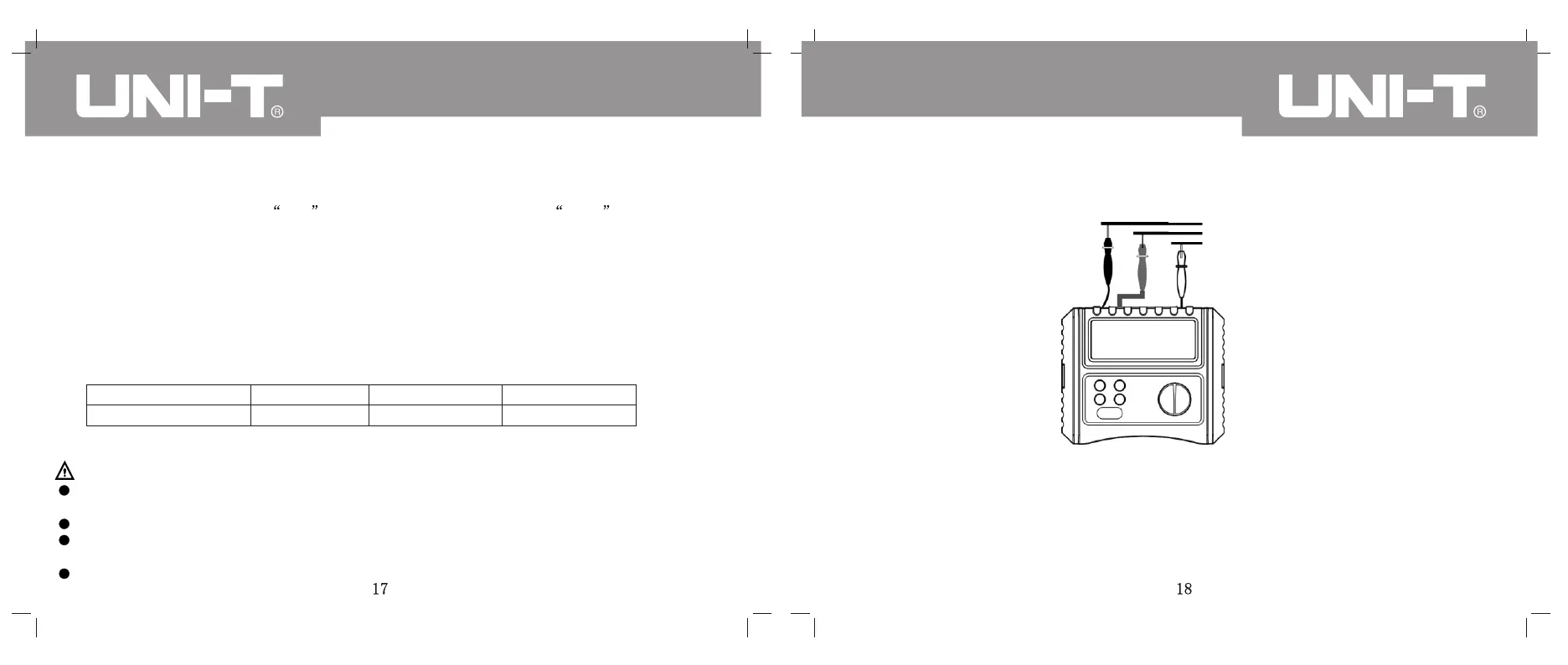
X. PHASE SEQUENCE AND PHASE LOSS MEASUREMENT
(SEE FIG. 6 FOR CONNECTION DIAGRAM)
L1
L2
L3
(Fig. 6)
Black
green
red
Make the rotary switch to Phase Rotary; correctly connect wires as per the Fig. 6 to make phase-
sequence and phase loss measurement.
Instructions on correct wiring operation: Connect red, green and black pens into the instrument
according to the corresponding color; then connect them to the corresponding phase:
In three-phase AC, black pen is connected to L1, green pen to L2 and red pen to L3; after
connection, the LCD immediately displays the phase sequence.
Results of rotation and phase loss