This document is a service manual for the UNI-T UTS1000/3000 Series Spectrum Analyzers, providing comprehensive information on their structure, maintenance, and troubleshooting.
Function Description
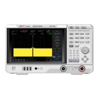
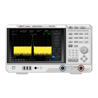
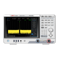
The UNI-T UTS1000/3000 Series Spectrum Analyzers are professional instruments designed for measurement purposes, specifically for spectrum analysis. They are used to analyze the frequency spectrum of electrical signals, providing insights into their composition and characteristics. The device features a display for visualizing the spectrum, a knob for navigation, and various buttons for controlling measurement parameters and modes. It supports different measurement modes such as Swept SA, and allows for adjustments of frequency, amplitude, and bandwidth settings.
Important Technical Specifications
The manual covers several models within the UTS1000/3000 series, including UTS1015E, UTS1015B, UTS1015T, UTS1032B, UTS1032T, UTS3021B, UTS3036B, UTS3084B, and UTS3084T.
Power Supply:
- AC Input Voltage: 100-240VAC (fluctuation ±10%) for 50/60Hz, and 100-120VAC (fluctuation ±10%) for 400Hz.
- Safety Class: Class I safety product, requiring a well-grounded power outlet.
Environmental Requirements:
- Indoor Use: Yes
- Pollution Degree: 2
- Altitude (Operating): Lower than 3000 meters
- Altitude (Non-operating): Lower than 15000 meters
- Operating Temperature: 0 °C to +40 °C
- Storage Temperature: -20 °C to +70 °C
- Humidity (Operating): Below +35°C ≤90% relative humidity
- Humidity (Non-operating): +35°C ~ +40°C ≤60% relative humidity
- Protection Level: 4kV for contact discharge and 8kV for air discharge against static electricity.
Components:
The device comprises several key assemblies:
- Rear Cover Assembly: Includes M4 inner torque screws, M12 nut, M3 inner torque screws, chassis rear cover assembly, and front-end components.
- Front Panel Components: Consists of M3 inner torque screws, cables (SMA torque wrench setting at 1.0N.m), front cavity of radio frequency board, RF PCBA board, RF board rear cavity, rear cavity of IF board, IF PCBA board, and front cavity of IF panel.
- Front Panel and Display: Features a knob cap, M3 inner torque screws, surface shell, LCD screen assembly, screen bracket, screen adapter board, silicone key set, and button board PCBA.
Usage Features
The spectrum analyzer is designed for professional users and institutions. It features a user-friendly interface with a display, a knob for precise adjustments, and dedicated buttons for various functions such as:
- Measurement Modes: FREQ, AMPT, BW, Marker, Trace, System, Sweep, Save, TG, Default, Auto, Peak, Touch, Lock.
- Frequency Settings: Center Frequency, Span, Start Freq, Stop Freq, Freq Offset, Full Span, Zero Span, Zoom Out, Zoom In, Last Span, CF Step, Auto Tune.
- Amplitude Settings: Ref Level, Atten, Preamp, Scale.
- Bandwidth Settings: RBW, VBW.
- Trace Settings: Trace (1, 2, 3, 4), Avg Type (Voltage), Avg | Hold.
- System Utilities: Correction (Off), Trig (Free Run), Freq Ref (In), Impedance (50Ω).
- Connectivity: USB flash disk insertion for data storage.
- Safety: The device is equipped with a grounding wire and requires proper grounding to prevent electric shock. It is recommended to use the supplied power cord and ensure it is not damaged.
Maintenance Features
The manual provides detailed instructions for both periodic and corrective maintenance.
Safety Precautions for Maintenance:
- ESD Protection: Electrostatic discharge (ESD) can damage semiconductor components. Always wear a grounded antistatic wrist strap and foot strap, and work in an antistatic environment. Minimize handling of static-sensitive circuit boards and components, and store them in static-protective containers.
- Qualified Personnel: Maintenance, adjustment, or parts replacement must be carried out by qualified personnel authorized by Unilever.
- Power Disconnection: Always cut off power before cleaning or disassembling the instrument.
External Cleaning:
- Case: Use a dry, lint-free cloth or a soft-bristled brush. For stubborn dirt, use a cloth or cotton swab dampened with a 75% isopropyl alcohol solution. Avoid abrasives.
- On/Standby Switch: Clean with a clean towel dampened with deionized water. Do not spray or wet the switch.
- Front Panel Buttons: Use only deionized water.
- Cabinet Parts: Use a 75% isopropyl alcohol solution.
- Display: Gently wipe with a clean-room wipe or non-abrasive cleaning cloth. For dirty displays, use distilled water, a 75% isopropyl alcohol solution, or a standard glass cleaner. Avoid excessive force, abrasive cleaners, and direct spraying of liquids.
Internal Cleaning and Inspection:
- Preventive Maintenance: Regular visual inspection and cleaning prevent instrument failure and increase reliability.
- Dust Cover Removal:
- Remove 4 screws fixing the dust cover and rear cover assembly using a T8 Torque screwdriver.
- Remove and clean the dust-proof net.
- Ventilation: Do not block ventilation holes. Ensure adequate ventilation with at least 15 cm clearance on all sides. Regularly check vents and fans.
Disassembly Procedures (for qualified personnel):
The manual details the removal and replacement of various modules, requiring specific tools like torque screwdrivers (T8, T10) and an SMA torque wrench.
- Rear Cover Removal:
- Disconnect all cables and power cords.
- Place the instrument face down on a cushion.
- Remove 2 screws on the case back cover assembly (T8 Torque screwdriver).
- Remove 8 screws on the case back cover assembly (T8 Torque screwdriver).
- Carefully lift the rear cover.
- Rear Cover Assembly Removal:
- Remove 10 upper and lower screws (T10 Torx screwdriver).
- Remove 4 screws on the left and right sides (T10 Torque screwdriver).
- Carefully lift the rear cover assembly and disconnect connecting wires.
- Power Module Removal:
- Remove 4 screws fixing the shielding cover (T10 Torque screwdriver).
- Disconnect power cord and fan wire.
- Remove 4 screws fixing the shield (T10 Torque screwdriver) and remove the power module.
- Fan Removal:
- Disconnect the fan wire from the power board.
- Remove screws fixing the fan on the rear cover assembly (T10 Torque screwdriver).
- RF Board Removal:
- Pull up two cables connecting the RF board to the IF board and remove the FPC cable.
- Remove SMA screws using a torque wrench.
- Remove 9 screws securing the cavity of the front cover assembly (T10 Torque screwdriver).
- Take out the cavity and remove screws fixing the RF board in the cavity (T10 Torque screwdriver).
- Digital IF Board Removal:
- Pull out two connecting cables to the RF board, and remove three FPC cables and external cables.
- Remove 13 screws fixing the digital IF board on the front cover assembly (T10 Torque screwdriver).
- Cover Disassembly:
- Remove the knob cap.
- Remove 9 screws fixing the front cover assembly (T10 Torque screwdriver).
- Display Removal:
- Remove 5 screws fixing the display (T10 Torque screwdriver).
- Carefully open the display screen and manually remove the FPC cable.
- Keyboard Deck Removal:
- Remove 8 screws fixing the display (T10 Torque screwdriver).
Calibration:
- Recommended Cycle: One year.
- Personnel: Calibration should only be performed by suitably qualified personnel.
Troubleshooting:
The manual includes a troubleshooting flowchart and a table of common symptoms with possible reasons, such as power cord issues, electricity failure, defective micro-controller components, faulty fan power cable, fan failure, and display circuit failure. Required equipment for troubleshooting includes a digital voltmeter and an anti-static working environment.
Warranty and Service:
- Warranty Period: One year from the date of shipment from authorized distributors for defects in materials and workmanship.
- Repair/Replacement: UNI-T will repair or replace defective products at its discretion.
- Contact Information: Users are directed to contact UNI-T Technology (China) Co., Ltd. for support, or local distributors/sales centers outside mainland China.
The manual emphasizes the importance of following all safety precautions to prevent personal injury, instrument damage, and ensure proper operation.