EasyManua.ls Logo

UNI-T UT60B User Manual

UNI-T UT60B
38 pages
To Next Page IconTo Next Page
To Previous Page IconTo Previous Page
Page #17 background image
l If reading with shorted test leads is not 0.5 , check for
loose test leads, incorrect function selection, or enabled Data
Hold function.
l For high-resistance measurement ( ), it is normal to
take several seconds to obtain a stable reading.
l The LCD displays indicating open-circuit for the tested
resistor or the resistor value is higher than the maximum
range of the Meter.
l When resistance measurement has been completed,
disconnect the connection between the testing leads and the
circuit under test, and remove the testing leads away from the
input terminals of the Meter.
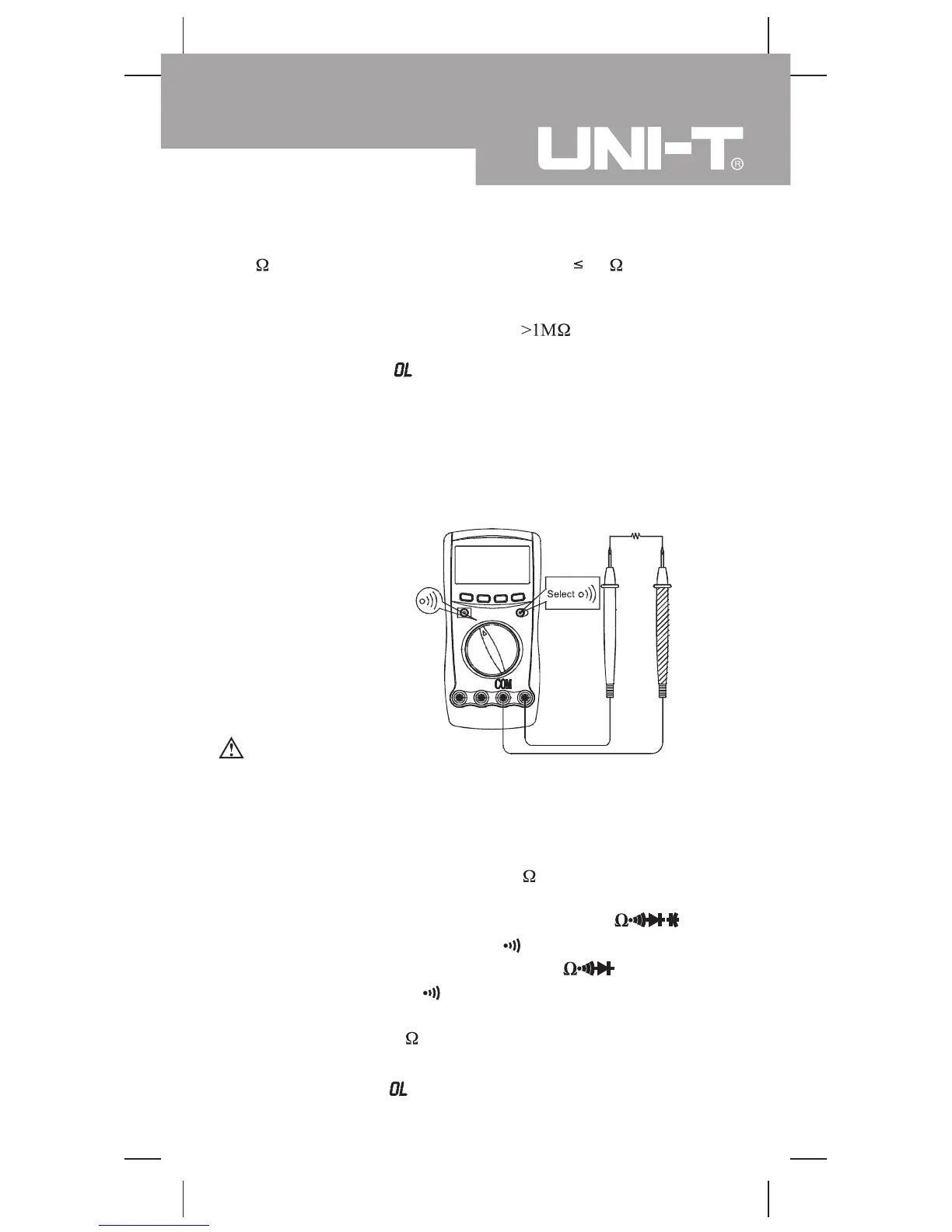
D.Testing for Continuity
(see figure 6)
Measurement Operation (4)
(figure 6)
BLUE button to select
To avoid damages to the Meter or to the devices under test,
disconnect circuit power and discharge all the high-voltage
capacitors before testing for continuity.
To test for continuity, connect the Meter as below:
1. Insert the red test lead into theHzV
terminal and the black
test lead into the COM terminal.
2. Model UT60C/UT60E: Set the rotary switch to
measurement mode.
Model UT60B: Set the rotary switch to and press
measurement mode.
3. The buzzer sounds if the resistance of a circuit under test is
less than around 70
Warning
and press BLUE button to select
Note
l The LCD displays indicating the circuit being tested is
open.
17
Model UT60B/C/E: OPERATING MANUAL
Question and Answer IconNeed help?

Do you have a question about the UNI-T UT60B and is the answer not in the manual?

UNI-T UT60B Specifications

General IconGeneral
TypeDigital Multimeter
DisplayLCD
Display Count1999
DiodeYes
Continuity BuzzerYes
TransistorYes
Data HoldYes
Full Icon DisplayYes
Sleep ModeYes
Low Battery IndicationYes
Input Impedance for DC Voltage Measurement10MΩ
Power Supply9V Battery
DC Current200μA/2mA/20mA/200mA
Resistance200Ω/2kΩ/20kΩ/200kΩ/2MΩ
Capacitance20nF/200nF/2μF/20μF
Frequency20kHz
Temperature-40°C to 1000°C

Summary

Rules For Safe Operation

DC Voltage Measurement Procedure

AC Voltage Measurement Procedure

Resistance Measurement Procedure

Continuity Testing Procedure

Diode Testing Procedure

Capacitance Measurement Procedure

Frequency Measurement Procedure

Duty Cycle Measurement Procedure

Temperature Measurement (UT60C/UT60E)

DC or AC Current Measurement Procedure

Current Measurement Operation Details

Hold Mode Operation

Relative Value Mode Usage

Accuracy Specifications: Voltage and Resistance

DC Voltage Accuracy

Details accuracy, resolution, and overload protection for DC voltage measurements.

AC Voltage Accuracy

Lists accuracy specifications, resolution, overload protection, and frequency response for AC voltage.

Resistance Accuracy

Details accuracy, resolution, and overload protection for resistance measurements, including REL mode.

Accuracy Specifications: Other Measurements

Continuity, Diode, Capacitance Accuracy

Specifies accuracy for Continuity, Diode, and Capacitance measurements.

Accuracy Specifications: Temperature and Current

DC Current Accuracy

Provides accuracy details, resolution, and overload protection for DC current measurements.

Accuracy Specifications: AC Current

AC Current Accuracy

Details accuracy, resolution, overload protection, and remarks for AC current measurements.

MAINTENANCE AND TROUBLESHOOTING

Fuse Testing Procedure

Explains how to test the internal fuses to determine if they are good or blown.

Battery Replacement

Fuse Replacement

RS232C Serial Port and Software (Model UT60E)

Related product manuals