14
Instructions for the installer
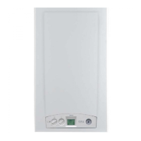
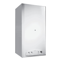
ALKON 24/35 B 60 WALL MOUNTING TEMPLATE
3.4 - BOILER LOCATION
When selecting the position for the installation of the boiler
please comply to the following safety requirements:
- Fit the appliance in rooms protected from frost;
- In rooms where aggressive vapours or dust are present,
the appliance must be able to operate independently from
the air of the location room;
- Do not use or leave explosive or easily inflammable mate-
rial (as for example: petrol, paint, paper) in the room whe-
re the appliance has been installed.
- The appliance must be installed exclusively on a vertical
and solid wall, capable of adequately supporting the wei-
ght of the boiler;
- The wall must not be made of inflammable material;
- Leave a clearance of 100 mm on each side of the boiler to
facilitate subsequent servicing;
Every appliance is supplied with a steel “Wall mounting tem-
plate” which, once fixed on to the wall chosen for the installa-
tion by means of the screw anchors supplied together with the
boiler, permits:
- Supporting the boiler;
- Marking the exact point for positioning the system pipework
connections:
• Gas supply
• Cold water feed
• Hot water outlet
• CH flow
• CH return
M = CH system flow ¾”
C = Hot water outlet ½”
G = Gas supply ¾”
F = Cold water supply ½”
156
S-C
237
S-R
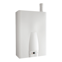
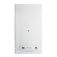
ALKON 24 B 60
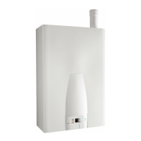
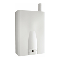
ALKON 35 B 60
R = CH system return ¾”
S-C = Condensate drain outlet Ø 32
S-R = CH safety relief valve drainage point
CM
199
190
90
FRG
600
140,568 68 117 59 147,5
290
50
780
884
65
58
120120
CM
199
190
90
FRG
600
140,5
68 68 117 59 147,5
290
50
780
884
65
43
120120

 Loading...
