34
Instruction for the installer
M
3
1
0
23
24
18
6
12
L
N
ON-OFF
4
M1
21 43
Low temperature zone High temperature zone
Boiler flow
Boiler return
Digital room controller
(low temperature
zone controller)
External voltage line
Room thermostat
(high temperature
zone controller)
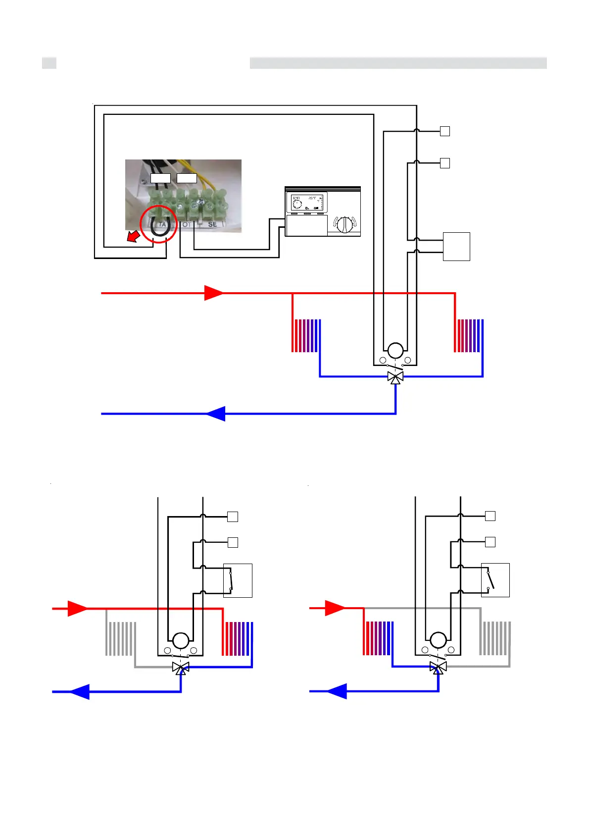
Layout of the electrical connections for zone control systems
Note: The terminal connections 3 and 4 in-
dicated in the diagram refer to the
valve’s internal limit stop, when the
same valve is in the “low temperatu-
re” position.
The microswitch on the 3-way valve closes whilst the room
thermostat is demanding heat when the diverter valve
reaches the “low temperature” position and sends the
request to the boiler.
The 3-way valve has to use the limit switch contact in order
to simulate this type of request.
When the thermostat’s contact (On-Off) is closed, the 3-
way valve opens the high temperature zone and closes the
low temperature zone (controlled by the digital room
controller “Regolafacile”).
With the thermostat’s contact (On-Off) open, the 3-way valve
deviates towards the low temperature zone (the
temperature value can be adjusted with the digital room
controller).
M
3
L
N
TA
4
LT z o n e
HT zone
Flow
Retur
External voltage line
To the terminals 1 and 2 on the M1 connector
M
3
LT zone
HT zone
Flow
Retur
External voltage line
L
N
TA
4
To the terminals 1 and 2 on the M1 connector

 Loading...