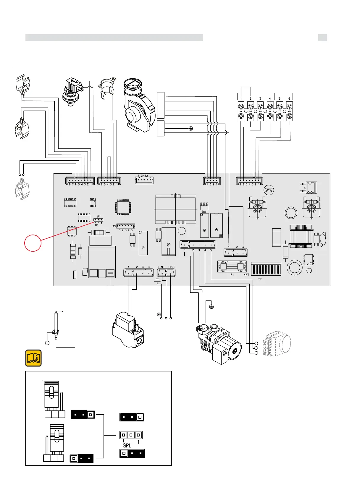
35
Instruction for the installer
A7...A18 = Connectors
DK = Safety pressure switch against lack of water
E. ACC./RIL. = Combined ignition/ionisation electrode
FL = Minimum flow switch
MVD = Motor of Diverting Valve (optional)
P = Circulating pump
SR = Heating flow temperature sensor
SRR = Heating return temperature sensor
SS = D.H.W. temperature sensor (for external storage
tank)
TL = Limit thermostat
VG = Gas valve
VM = Modulating fan
SE = Terminals for outer temperature sensor
OT = Terminals for Modulating Room Thermostat
(REGOLAFACILE)
TA = Terminals for ON-OFF Room Thermostat
FUNCTIONAL FLOW WIRING DIAGRAM ALKON 09 R 18 - R 24
YEL/GREEN
YEL/GREEN
LIGHT BLUE
G
TL
DK
WHITE
BROWN
LIGHT BLUE
P
230 V-50 Hz
E.ACC./RIL.
SE
OT
TA
A14
A15
BLACK
BLACK
WHITE
WHITE
YELLOW
YELLOW
BLACK
A7
A16
A18
A17
LIGHT BLUE
BROWN
YEL/GREEN
N
L1
BROWN
LIGHT BLUE
BROWN
MDV
RED
(CH)
WHITE
(DHW)
GREEN
M
5
2
4
1
BROWN(PWM)
BLUE (TACHO)
BLACK
ORANGE
1
2
3
YEL/GREEN
LIGHT BLUE
BROWN
A13
LIGHT BLUE
T5
RED
A12
SS
LIGHT BLUE
BROWN
SRR
GREEN
GREEN
SR
WHITE
WHITE
BLACK
Note:
The figures shown on the above wiring
diagram are purely indicative
JP1
3.16 - WIRING DIAGRAMS
JP1: selection type of gas: NATURAL - GPL
Jp1
GPL
NATURAL

 Loading...