11
General info
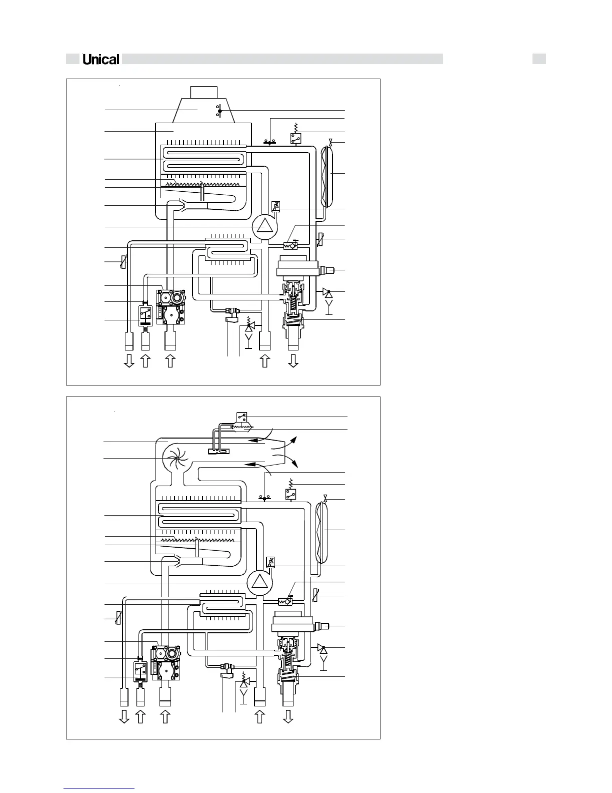
fig. 7
EVE 05 CTN 24
EVE 05 CTFS 24
fig. 6
1
3
2
4
5
6
7
8
9
10
11
12
13
14
15
16
17
18
19
20
21
22
23
2425
C
F
GR
M
C
F
GR
M
1
3
2
4
5
6
7
8
9
10
2526
17
18
19
20
21
22
23
24
11
12
13
14
16
15
1 Flow switch - Cold water filter
2 D.H.W. flow restrictor
3 Gas valve
4 D.H.W. temperature sensor
5 Plates heat exchanger for DHW
production
6 Circulating pump
7 Burner nozzles
8 Ionisation/Ignition electrode
9 Burner
10 Monothermal heat exchanger
11 Combustion chamber
12 Flue gas manifold/down-draught
diverter
13 Flue gas anti-spillage thermostat
14 H.L. thermostat
16 Expansion vessel inflating valve
17 Expansion vessel
18 Automatic air vent
19 By-pass
20 C.H. temperature sensor
21 Diverting valve motor
22 Boiler drain cock
23 Diverting valve
24 Heating circuit safety valve
25 Filling valve
C D.H.W. outlet
F D.C.W. inlet
G Gas inlet
R C.H. system return
M C.H. system flow
1 Flow switch - Cold water filter
2 D.H.W. flow restrictor
3 Gas valve
4 D.H.W. temperature sensor
5 Plates heat exchanger for DHW
production
6 Circulating pump
7 Burner nozzles
8 Ionisation/Ignition electrode
9 Burner
10 Monothermal heat exchanger
11 Flue gas extractor fan
12 Air/flue coaxial duct
13 Micro-switch on flue gas pressure
switch
14 Flue gas pressure switch
15 H.L. thermostat
16 Minimum water pressure switch
17 Expansion vessel inflating valve
18 Expansion vessel
19 Automatic air vent
20 By-pass
21 C.H. temperature sensor
22 Diverting valve motor
23 Boiler drain cock
24 Diverting valve
25 Heating circuit safety valve
26 Filling valve
C D.H.W. outlet
F D.C.W. inlet
G Gas inlet
R C.H. system return
M C.H. system flow
 Loading...