15
Installation info
2.2.3 - ASSEMBLING THE BOILER
Before connecting the boiler to the D.H.W. and
heating system pipes, carefully clean the pi-
pes to remove all traces of metal resulting from
processing and welding operations as well as
any oil and grease which could damage the
boiler or jeopardize its operation.
To install the boiler:
- Fix with tape the paper template to the wall;
- make two Ø 12 holes in the wall and insert
the dovels;
- position the junction points for the connect-
ion of the gas supply pipe, cold water sup-
ply pipe, D.H.W. outlet, CH flow and return
in the positions shown by the template. ;
- fit the boiler onto the support hooks;
Do not use solvents which
could damage the
components.
Unical refuses all liability for
injury to persons and animals or
damage to property resulting
from non-observance of the abo-
ve.
- connect the boiler to the gas pipe,
domestic cold and hot water pipes, CH flow
and return pipes.
- connect to electrical supply
2.2.4 - VENTILATION
The boiler must be installed in a suitable room
according to the rules in force and particular-
ly:
NATURAL DRAUGHT OPEN FLUE BOILERS
(TYPE B11bs and VMC INSTALLATIONS)
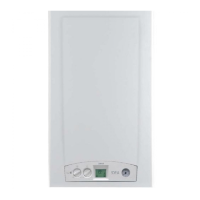
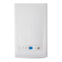
The boilers EVE 05 CTN 24 F, EVE 05 RTN 24,
EVE 05 CTN 24, are open flue boilers and are
foreseen for chimney connection: the air for
combustion is taken directly from the room in
which the boiler is installed.
The room can have both a direct ventilation
(i.e. with ventilation openings facing out-
wards) or an indirect ventilation (i.e. with ven-
tilation openings facing an adjacent room) pro-
vided that the following requirements are com-
plied with:
Direct ventilation:
- The room has to have a ventilation open-
ing of, at least,
6 cm² /kW of installed input (see input ta-
ble on par. 2.7) and, in no case, lower than
100 cm² and made directly onto an exter-
nal wall.
- The opening has to be as close as possi-
ble to the floor.
- It should not be possible to close it and it
should be protected with a grate not redu-
cing its usefull ventilation section.
- A correct ventilation can be optained also
through the addition of more openings, pro-
vided the addition of the different sections
is not less than that really needed.
connection duct to the draught diverter.
- starting from the draught diverter, the duct
must have a vertical section with a length
more than twice the diameter, before get-
ting into the chimney.
2.2.5 - FLUE GAS DISCHARGE
SYSTEM
NATURAL DRAUGHT OPEN FLUE BOILERS
Connection to the chimney
A good chimney is very important for the cor-
rect functioning of the boiler; it must therefore
conform with the following requirements:
- it must be made from waterproof material
and be resistant at the temperature of the
flue gas and relative condensate;
- it must have sufficient mechanical
strength and low thermal conductivity;
- it must be perfectly sealed to prevent cool-
ing due to parasite air inlets;
- it must be as vertical as possible and the
end section must have a chimney cap
which guarantees efficient and constant
evacuation of the combustion products;
- the chimney must have a diameter not
smaller than that of the boiler’s draught di-
verter; for chimneys with a square or
rectangular section, the internal section
must be 10% larger than the section of the
- In case it is not possible to make a venti-
lation opening close to the floor, it will be
necessary to increase its usefull section
of at least 50%.
- If an open fire is present in the same room
it needs an indipendent air supply, other-
wise the installation of a type B appliance
is not permitted.
- If in the room there are other devices
which need air for their operation (e.g. a
wall exhauster) the section of the ventila-
tion opening has to be the properly sized.
Indirect ventilation
In case it is not possible to make a room ven-
tilation opening on an external wall, it is pos-
sible to have an indirect ventilation, sucting
the air from an adjacent room, making an
opening in the lowest part of a door.
This solution is possible only if:
- The adjacent room is not a bed room
- The adjacent room is not a common part
of the building and is not a room with fire
danger (e.g. a fuel deposit, a garage, etc..)
FORCED DRAUGHT ROOM SEALED BOI-
LER
(TYPE C12 - C32 - C42 - C52 - C62 - C82)
The EVE 05 CTFS 24 F - EVE 05 RTFS 24 -
EVE 05 CTFS 24 are forced draught, room seal-
ed boilers; so they do not need particular ven-
tilation openings for the combustion air, in the
room in which they are installed.
FORCED DRAUGHT, OPEN FLUE BOILER
(TYPE B22)
If the EVE 05 CTFS 24 F - EVE 05 RTFS 24 -
EVE 05 CTFS 24 are installed in a room ac-
cording to the chimney configuration on type
B22, the same ventilation requirements esta-
blished in paragraphs Direct ventilation and
Indirect ventilation apply.

 Loading...


