33
Service info
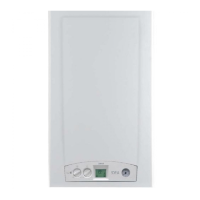
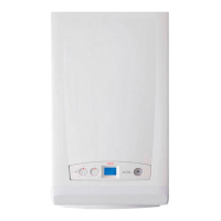
fig. 34
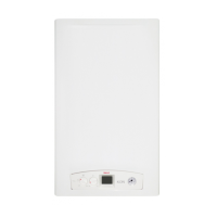
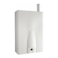
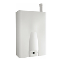
EVE 05 CTN 24 F - EVE 05 CTN 24 F- EVE 05 CTFS 24 F - EVE 05 CTFS 24
EVE 05 RTN 24 - EVE 05 RTFS 24
A = Manometer
B = Summer / Winter switch + C.H. tempe-
rature control
C = D.H.W. temperature control (only for
combi C version)
D = Reset button / chimney sweeper
/ diagnostics
F = CH mode active
G = DHW mode active
I = Lock out
L = Burner in operation
M = Failure
N = Temperature or failure code indication
Summer/Winter switch + C.H.
temperature control (B)
You can select which mode to
use by turning this knob.
If the knob is in the following po-
sition – – it indicates that
the boiler is working only for do-
mestic hot water production and
that the temperature can be adju-
sted turning knob ''C''.
If the knob is set within the ran-
ge indicated by the arrow on the
illustration it means that the boi-
ler always gives priority to the pro-
duction of domestic hot water (if
it is requested) and controls the
temperature of the water of the
heating circuit from a minimum
of 45°C to a maximum of 78°C.
D.H.W. temperature control
(C) (Only for EVE 05 CTN 24
F - EVE CTFS 24/28 F)
If the knob is set within the ran-
ge indicated by the arrow on the
illustration it means is possible
to adjust the domestic hot
water temperature. The
temperature can be controlled
from a minimum of 35°C to a
maximum of 57°C.
By adjusting the Domestic
Hot Water temperature to the
real required temperature,
you will avoid to mix hot
BD ACE
BD AE
MAX
M
I
N
MAX
M
I
N
water with cold water, in this
way reducing both the
boiler operation costs and
the scaling formation.
MAXMIN
fig. 35
°C
F
G
L
I
M
°C
®
MAX
MAXMIN
M
I
N
EVE
05
°C
®
MAX
MAXMIN
M
I
N
EVE
05
N
USERS' INSTRUCTION
3.1 - CONTROL PANEL
3

 Loading...


