20
Installation info
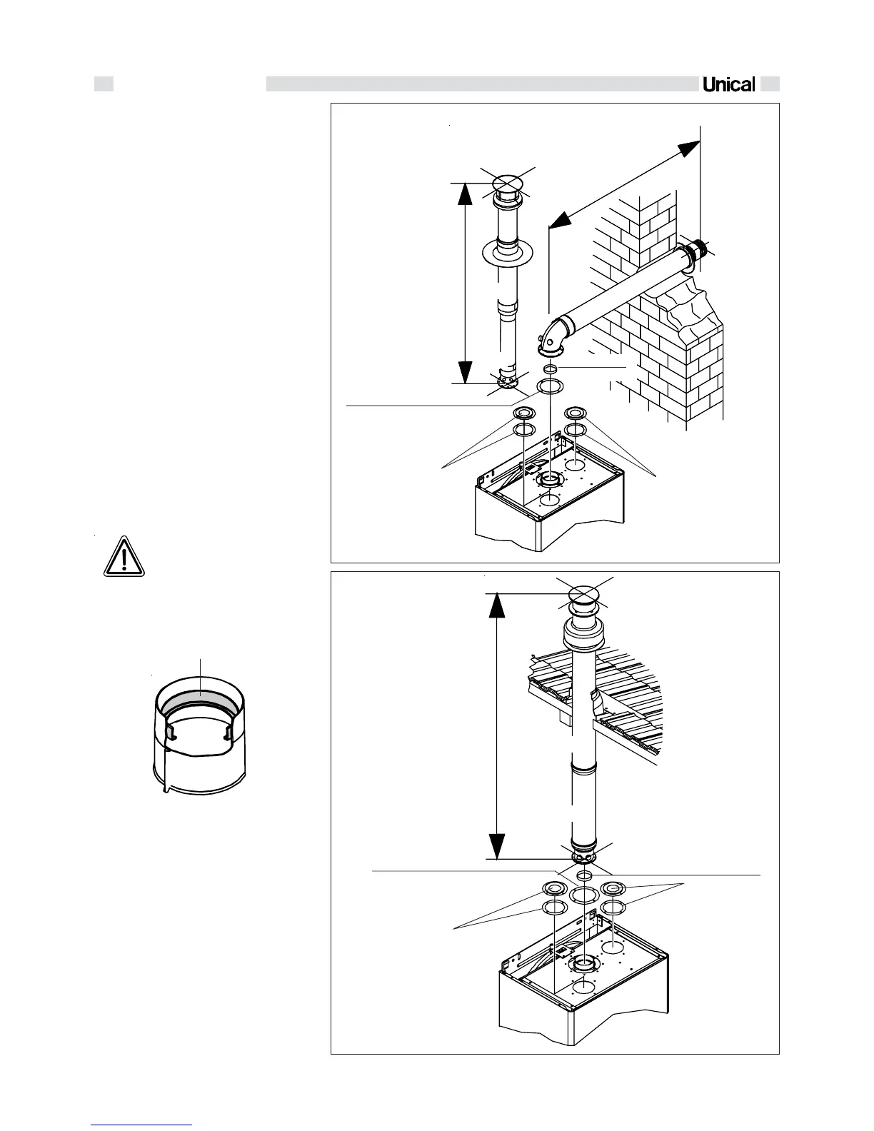
fig. 15
fig. 16
Ø 80/125
Ø 80/125
Ø 60/100
Ø 80/125
Rubber foam gasket
Up to 2 m
Up to 1 m
Up to 2,5 m
Rubber foam
gasket
Diaphragm Ø 42
Diaphragm
Ø 42
2.2.9 - DISCHARGE OF FLUE
GAS INTO
COAXIAL DUCTS
Ø 100/60 mm
Type C12 Ø 100/60 mm
The minimum length of horizontal coaxial
ducts is 0.5 metres. The maximum allowable
length of horizontal co-axial ducts is 3 me-
tres; for each additional bend the maximum
allowable length must be reduced by 1 metre.
Moreover, the duct must have a downward dip
of 1% towards the outlet point to prevent rain
water from getting into the duct.
Type C32 100/60 mm
The minimum length of vertical coaxial ducts
is 0.5 metres. The maximum allowable length
of vertical coaxial ducts is 4 metres exclu-
ding the stack (Ø 80/125); for each additional
bend the maximum allowable length must be
reduced by 1 metre.
The diaphragm Ø 42 supplied with the boi-
ler must be inserted in the flue gas exhaust
pipe as shown in figure 15, for installa-
tions with horizontal coaxial pipe up to 1
m and with vertical coaxial pipe up to 2
m.
VERTICAL FLUE DUCT WITH
COAXIAL DUCT Ø 80/125
Tipo C32 Ø 80 / 125
The minimum length of vertical coaxial ducts
is 1,2 metres. The maximum allowable length
of vertical coaxial ducts is 6 metres exclu-
ding the stack (Ø 80/125); for each additional
bend the maximum allowable length must be
reduced by 1 metre.
The diaphragm Ø 42 supplied with the boi-
ler must be inserted in the flue gas exhaust
pipe, as shown in figure 16, for installa-
tions with a coaxial pipe up to 2,5 m.
Fitting of the diaphragm Ø 42
Closing cover
with gasket in
neoprene
Closing cover
with gasket in
neoprene
Closing cover
with gasket in
neoprene
Closing cover
with gasket in
neoprene
WARNING: For the smoke ou-
tlet configuration (see fig. 15-
16) it is necessary to close the
holes of air entry ''1-2'' with
the provided for closing co-
vers and the gaskets delive-
red with the boiler.
 Loading...