11
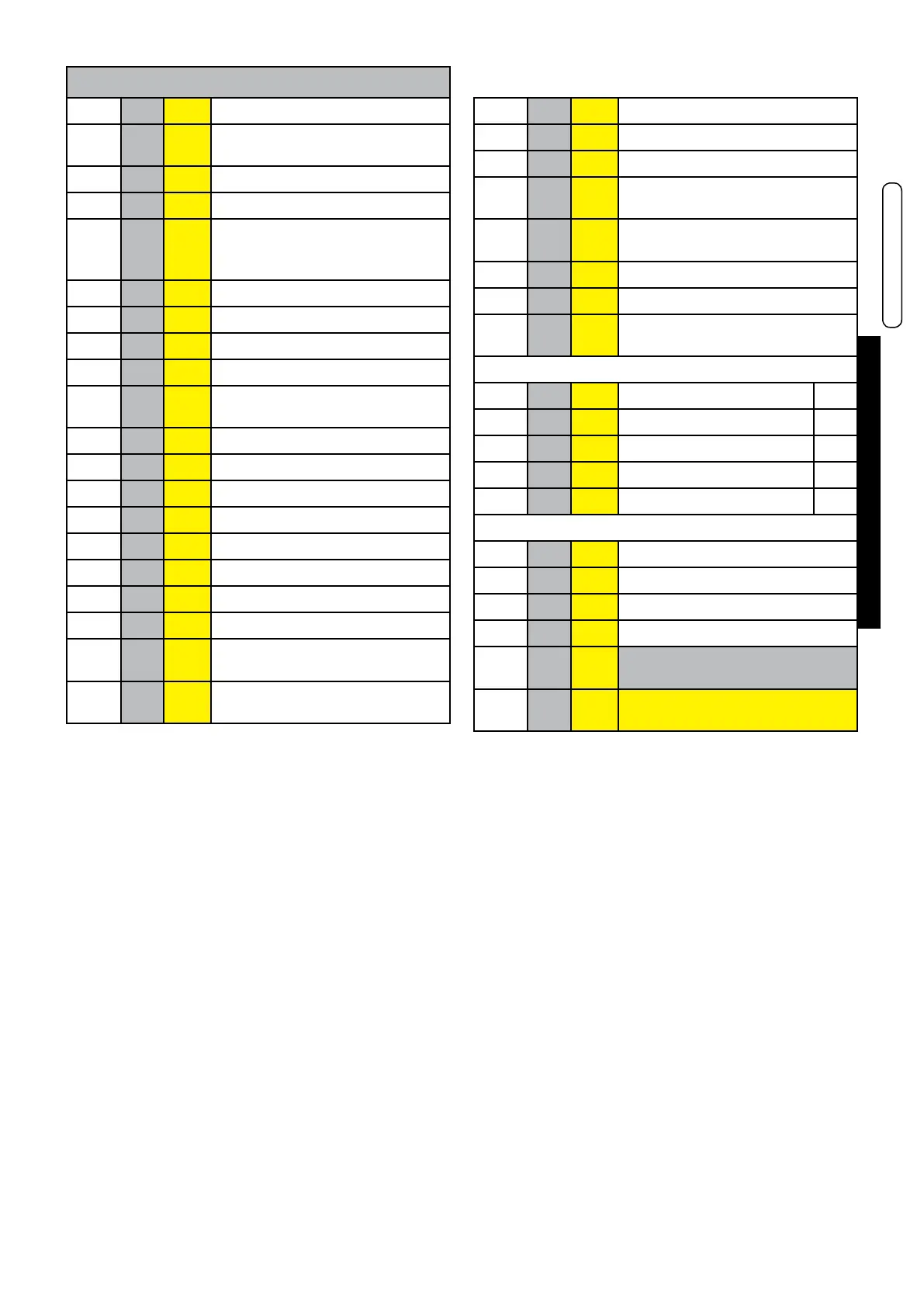
Technical Features
ENGLISH
KEY
NO. C.E. S.E. Description
1 db SS Domestic hot water temperature
sensor
2 FLS Flow switch with cold water lter
3 VG Gas valve
4 Fd E.
ACC
/RIL
Ignition/detection electrode
5 Burner
6 Combustion chamber
7 AF TF Flue gas anti-overow thermostat
8 Expansion vessel
9 FR
HT
Heat exchanger
10 HL TL Safety thermostat
11 Hb SR Heating temperature sensor
12 Ht P Pump
13 Lp DK Water deciency pressure switch
14 Boiler drain valve
15 Filling valve
16 Diverter valve
17 Plate heat exchanger
18 FL
FH
VM
Fan
19 AF
AS
PV Flue gas pressure switch
20 Safety valve
21 Automatic by-pass
22 rb SRR Return temperature sensor
23 tf TLC Flue gas collector safety ther-
mostat
24 Aluminium Heat Exchanger/Ca-
pacitor
25 Vent valve
26 Condensation drain trap
27 SL Arrangement for condensate
sensor level
C Domestic hot water outlet G ½
G Gas inlet G ¾
F Cold water inlet G ½
M Heating system ow G ¾
R Heating system return G ¾
Rc Filling valve
Sc Boiler drain
Svs Safety valve drain
Scond
Condensation drain
C.E. = ERROR CODES see
par. 4.6
S.E. = WIRING DIAGRAM KEY
see par. 4.5

 Loading...