UM982eb User Manual
14 UM982 Peripheral Design UC-08-M31 EN R1.0
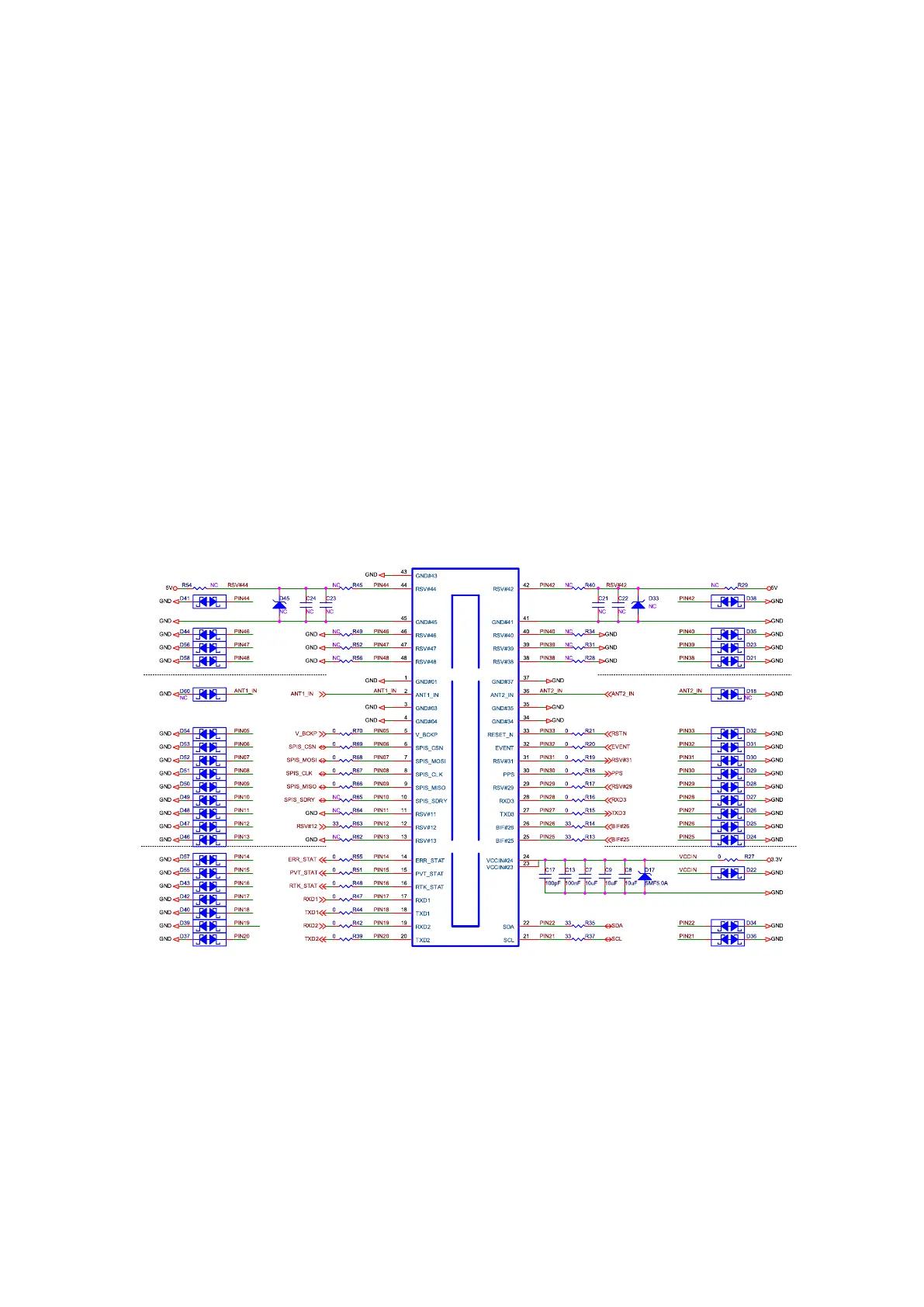
6 UM982 Peripheral Design
TVS anti-surge protection is added at the input of the UM982 module. ESD protection is
added at all pins.
Use large and small VCC filter capacitors together, with a total capacitance greater than
30 uF.
Add series resistors at the IO pins for the convenience of debugging.
VCCIN powers the UM982 module only. R27 is a large-size resistor (with high rated power)
to ensure the current capability. In the figure below, a 0805 resistor is used.
Removing R27, connecting a power supply wire at TP1 and a ground wire at TP3 (as
shown in Figure 7-1), you can use an external power to supply the module. This method
can be used to measure the input voltage and current of UM982.
Figure 6-1 UM982 Peripheral Design
Silkscreen markings are printed around the UM982 module to identify the resistors, which
is convenient for measurement.