UM982eb User Manual
16 Debug Support UC-08-M31 EN R1.0
7 Debug Support
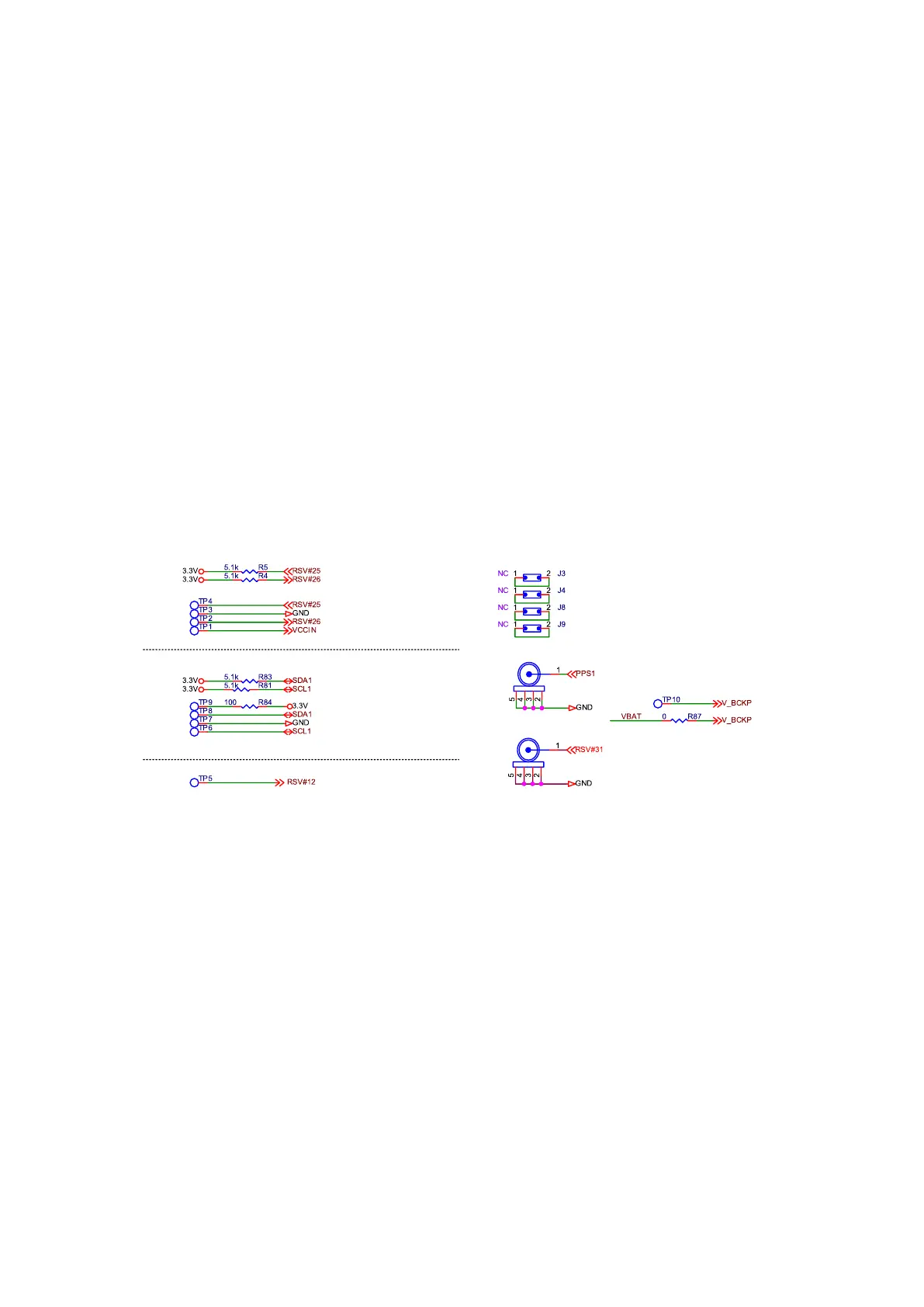
As mentioned above, TP1 and TP10 can be used to connect an external power to supply
VCCIN and V_BCKP and to measure the supply voltage and current.
TP2, TP4, TP6 and TP8 are used for internal debugging, of which TP6 and TP8 can be
used to debug I
2
C.
J1 and J2 are used for MMCX connection. After soldering the MMCX connector, it can be
used to measure the PPS signals.
J3, J4, J8 and J9 are debug ports. Connect the signal that needs to be tested to the square
hole and test the round hole, or connect the round hole to a measuring instrument. Using
these debug ports can avoid damage to the PCB pads and traces, which is convenient for
debugging.