UM982eb User Manual
8 Power Supply UC-08-M31 EN R1.0
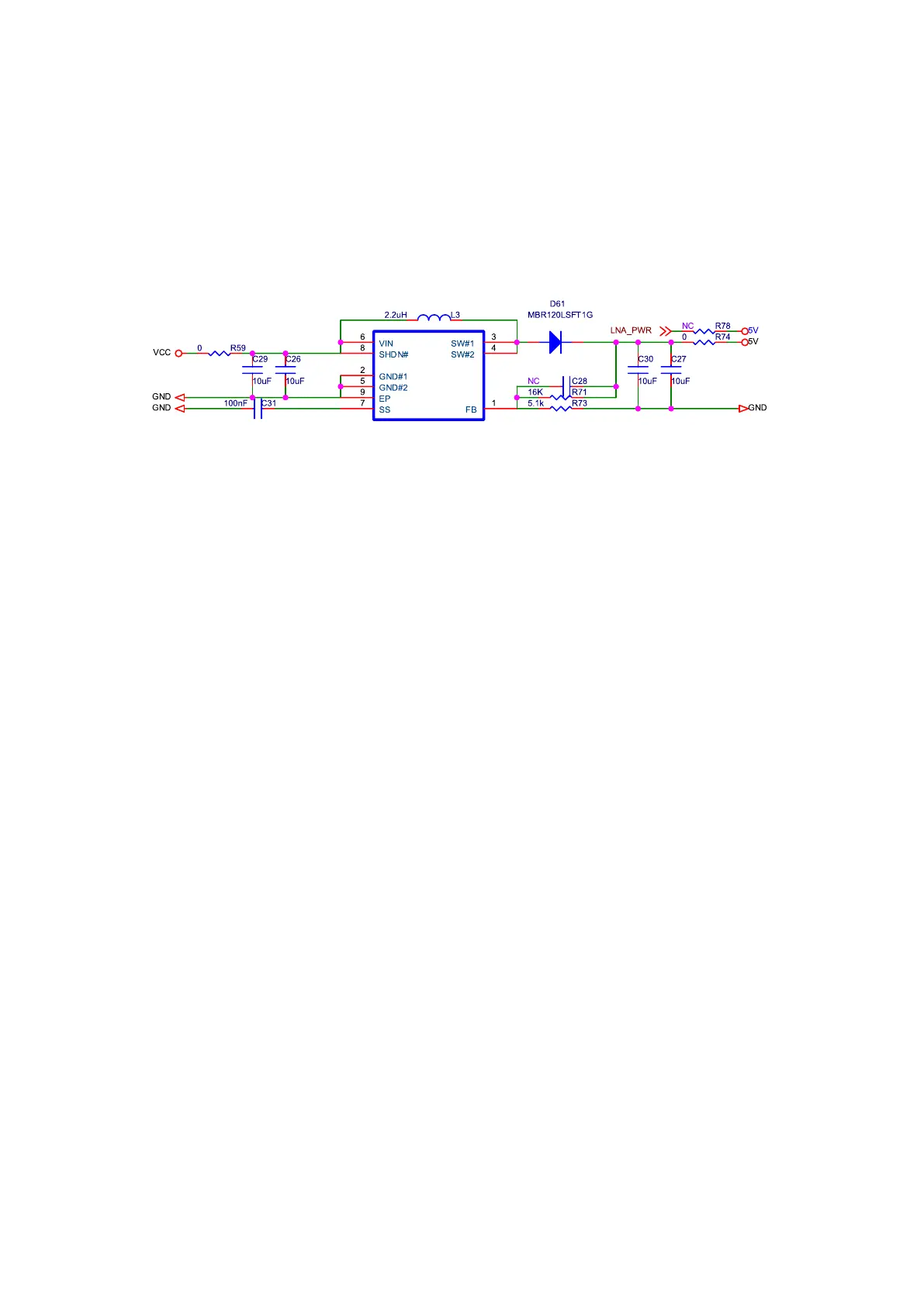
3.2 5V DC/DC Power Supply
VCC outputs 5 V voltage after passing through the DC/DC boost circuit to feed the
antenna.
Figure 3-4 5V DC/DC Boost Circuit
Note:
You can choose whether to use the 5 V power on the board to feed the antenna according
to the antenna type.
R59 and R74 are series resistors connected to the DC/DC circuit at the input and output,
which are used for debugging. When selecting the resistors, choose those with suitable
rated power according to the power consumption of the antenna load. Here a 0603 0-ohm
resistor is selected.
R78: After removing R59/R74 and soldering R78, you can use the external LNA_PWR to
feed the antenna.