UC-08-M31 EN R1.0 Antenna circuit 11
Figure 4-2 Antenna Short Protection Circuit on the Bottom of UM982eb
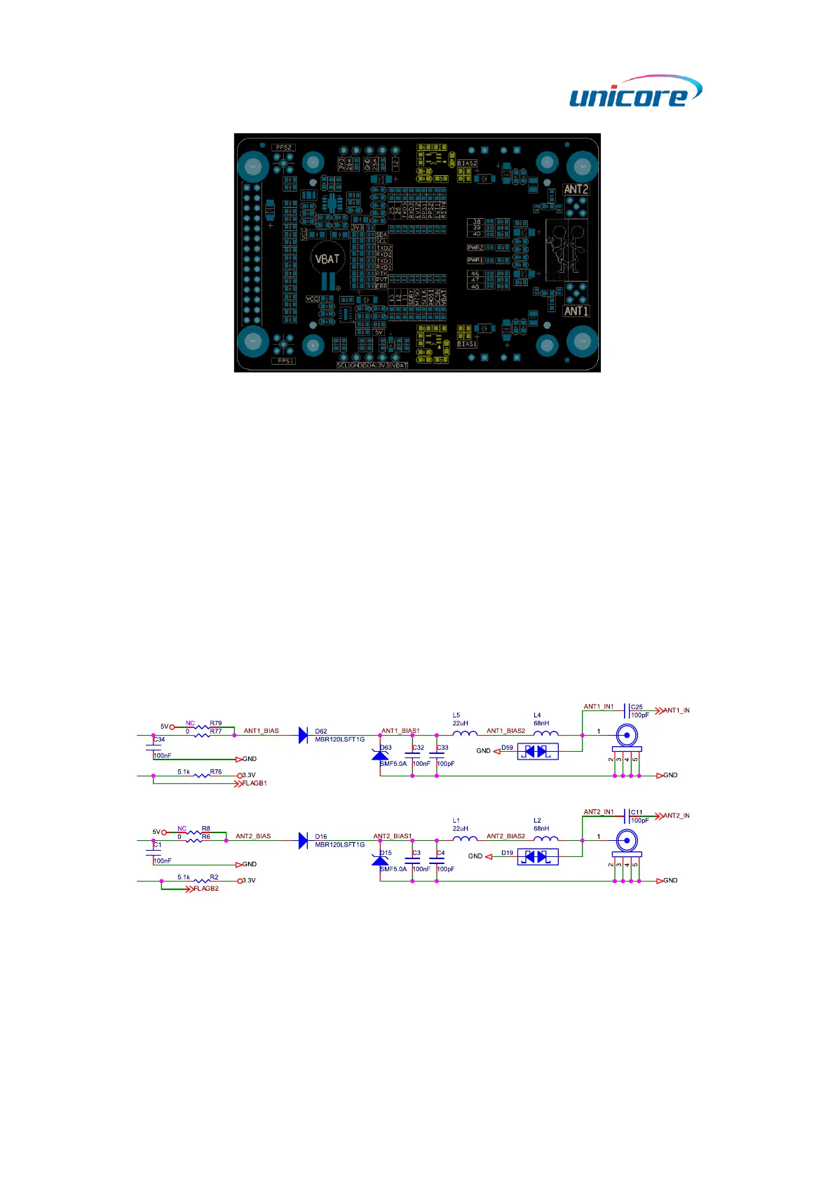
4.2 Antenna Feed Circuit
The antenna feed circuit consists of the anti-reverse current design, anti-surge design,
filter inductors, and ESD protection.
Removing R77 and R6 and soldering R79 and R8, you can directly use the 5 V power to
supply the antenna. In this condition, the antenna short protection circuit on UM982eb
will be bypassed.
The ESD protection diode should support high-frequency signal (above 2000 MHz).
Nexperia PESD5V0F1BL is recommended here.