UNIDEN 2020
Sid 10 (26)
4. TRANSMITTER RF CIRCUITS ALIGNMENT
4-1. Test Equipment Required
(1) RF Power Meter.
4-2. Tuning Coil Adjustment
*(1) Obtain maximum output at each frequency in chart 4-2-1-A, but note that
PRESELECT CONTROL should be center position.
(2) Set METER SWITCH to ALC.
(3) Turn CARRIER CONTROL knob fully clockwise.
(4) Set STANDBY SWITCH to MANU.
(5) Adjust each coil in chart 4-2-1-B to get the maximum meter reading.
(6) Return CARRIER CONTROL counterclockwise so as to make tuning more
easily upon adjustment.
(7) Repeat (1) to (6) procedures on each band in order as show in the
chart 4-2-1.
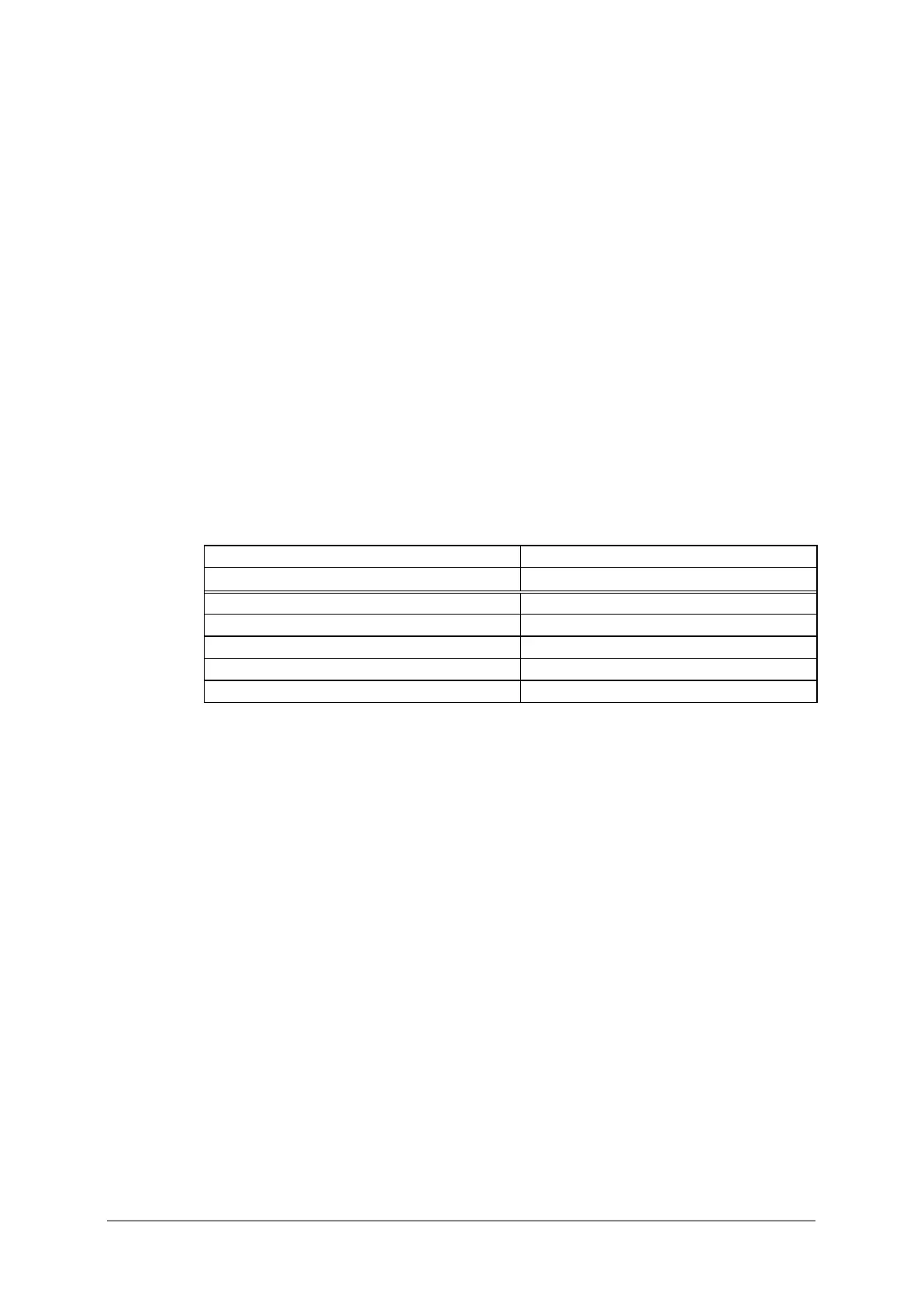
Chart 4-2-1
A B
Adjusting Frequency (MHz) Adjusting Coil No.
3.600 L251, L252, L259
7.100 L253, L260
14.200 L254, L261
21.200 L255, L262
28.500 L256, L263
 Loading...