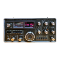
UNIDEN 2020
Sid 9 (26)
3-4. Modulator Output Coil Adjustment
(1) Connect RF VTVM to Pin 6 of J16 (IF UNIT).
(2) Set RF AMP SWITCH on the rear panel to OFF.
(3) Set MODE SWITCH to TUNE.
(4) Turn CARRIER CONTROL knob fully clockwise.
(5) Set STANDBY SWITCH to MANU.
(6) Adjust L501 for maximum VFVM indication. It will indicate around
0.2V r.m.s.
(7) Reset CARRIER CONTROL fully counter-clockwise and STANDBY
SWITCH to PTT.
(8) Connect AG output to the microphone jack and provide 1,500 Hz, 10 mV
output.
(9) Set MODE SWITCH to USB.
(10) Turn MIC GAIN CONTROL fully clockwise.
(11) Set STANDBY SWITCH to MANU.
(12) Adjust L504 for maximum meter indication. It will indicate around
0,3V r.m.s.
3-5. Balanced Modulator Alignment.
(1) This alignment should be taken place after completion of OUTPUT METER
adjustment (5-1, 5-2).
*(2) Obtain maximum output at 14.2 MHz.
(3) Set MODE SWITCH to USB.
(4) Connect RF meter to antenna jack.
(5) Make sure that MIC GAIN CONTROL is set fully counter-clockwise.
(6) Set STANBY SWITCH to MANU and adjust R530 for the minimum meter
indication.
(7) Change MODE SWITCH to LSB and USB by yurns, and make presise
tuning by adjusting R530 to get equal meter readings on both modes.
3-6. AM Modulation Adjustment
(1) This alignment also should be made after completion of OUTPUT METER
adjustment (5-1, 5-2).
*(2) Obtain maximum output at 14.2 MHz.
(3) Set MODE SWITCH to AM
(4) Set STANDBY SWITCH to MANU.
(5) Turn CARRIER CONTROL to get 120 mV reading on the meter.
(6) Connect AG output to microphone jack and provide 1,500 Hz, 10 mV
output.
(7) Set MIC GAIN CONTROL to 3 o’clock position.
(8) Use Oscilloscope to observe output envelope.
(9) Adjust R509 to keep about 80% of output modulation level.

 Loading...