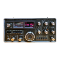
UNIDEN 2020
Sid 13 (26)
LOCAL OSCILLATOR CIRCUITS ALIGNMENT
1. VFO UNIT (PC-083, PC-084) ALIGNMENT
1-1. Test Equipment Required
(1) Frequency Counter
(2) RF voltage Meter (RF VTVM)
1-2. Oscillator Frequency Adjustment.
(1) Set FUNCTION SWITCH to INT
(2) Set R.I.T SWITCH to OFF
(3) Connect Frequency Counter to Pin 5 J701.
(4) Turn the main dail nd set it to 00 KHz (toward 90 kHz, 100 kHz), then adjust
L702 to get 9,038 kHz counter reading.
(5) Then turn the dial to 00 kHz (toward 10 kHz), and adjust trimmer C707 to
get 9,138 kHz counter readings.
(6) Repeat (4) and (5) adjustments until both readings are made correctly.
1-3. Output Voltage Adjustment.
(1) Set switches to same as 1-2 adjustment.
(2) Connect RF meter to Pin 5 of J701.
(3) Turn and set the dial to 50 (center) readings.
(4) Adjust L706 and L707 to get maximum meter readings. It will indicate
around 0.4 – 0.5V r.m.s.

 Loading...