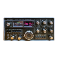
UNIDEN 2020
Sid 15 (26)
3. LOCAL OSCILLATOR UNIT (PC-092) ALIGNMENT.
3-1. Test Equipment Required
(1) RF Voltage Meter.
(2) Frequency Counter.
(3) Sweep Generator.
(4) Oscilloscope.
3-2. Xtal Oscillator Output Adjustment.
(1) Connect RF voltage meter to TP102.
(2) Select BAND SWITCH in order, starting from 15.0 MHz, according to
chart 3-2-1-A and adjust each coils in 3-2-1-B so as to get 1.5V r.m.s. meter
readings, respectively.
Chart 3-2-1
A B C D
BAND COIL (see 3-2) Freq. (see 3-3) TRIMMER (see 3-3)
15.0 L101 37.025 MHz C116
3.5 L102 25.525 C117
7.0 L103 29.025 C118
14.0 L104 36.025 C119
21.0 L105 43.025 C120
28.0 L106 50.025 C121
28.5 L107 50.525 C122
29.0 L108 51.025 C123
29.5 L109 51.525 C124
27.0 L110 49.025 C125
3-3. Xtal Oscillator Frequency Adjustment.
(1) Connect Frequency Counter to TP102 through 1pF capacitor.
(2) Select BAND SWITCH in order starting from 15.0 MHz according to the
chart 3-2-1-A and adjust each trimmer in 3-2-1-D so as to obtain frequency
readings as shown in 3-2-1-C respectively.
3-4. VCO Buffer Amplifier Adjustment.
(1) Connect RF voltage meter to DRAIN of Q113.
(2) Set BAND SWITCH to 3,5 MHz.
(3) Set SEGMENT SWITCH to 200/700 kHz.
(4) Turn and set the dial to 50 (center) readings.
(5) Adjust L121 and L122 to get maximum meter readings.

 Loading...