UNIDEN 2020
Sid 16 (26)
3-5. Bandpass Filter Adjustment.
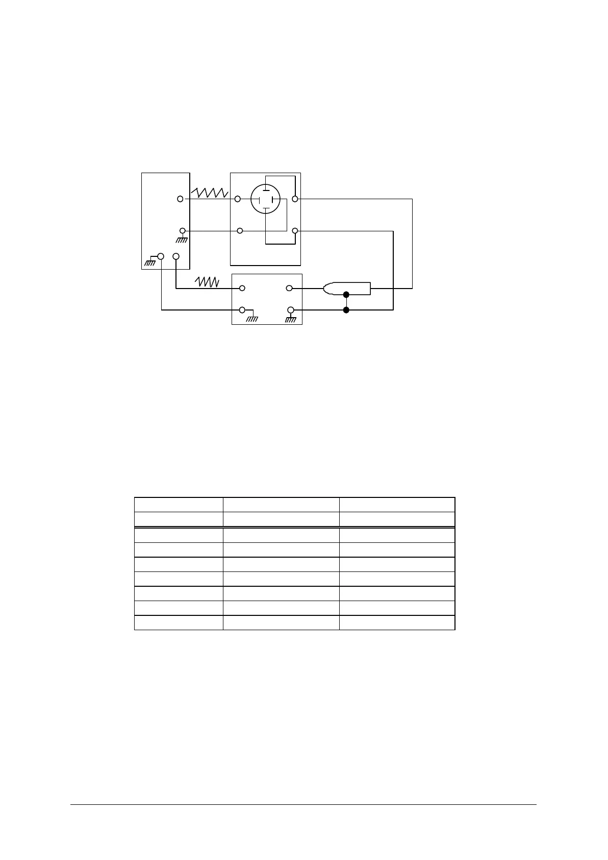
(1) Connect test equipments as show in Fig 3-5-1
Fig 3-5-1
Oscilloscope
TP101
Sweep
Generator
J104 (1)
H V
(2) Select BAND SWITCH in order, starting from 15.0 MHZ according to the
chart 3-5-1 and adjust each coil (3-5-1-C) so as to get the assigned wave from on
oscilloscope (3-5-1-B) respectively.
(3) After completion of these adjustments, remove sweep generator and
oscilloscope. Then, connect RF voltage meter to Pin 1 of J104 and confirm that
meter readings on each band show 0.7 – 1.3V r.m.s.
Chart 3-5-1
A B C
BAND WAVE FORM COIL
15.0 Fig. 3-5-2 L123, L130
3.5 3-5-3 L124, L131
7.0 3-5-4 L125, L132
14.0 3-5-5 L126, L133
21.0 3-5-6 L127, L134
28.0 3-5-7 L128, L135
28,5 3-5-8 L129, L136
 Loading...