4 319 2366 02/4
7842m b11/1200
RPO...
LN MB1B2MU3G2
Q4 Q5
*
U3
B1MB2MG2
Q4
Q5
3x1,5m m
2
GND
separat verlegen
lay cables separately
p o s e r le s c â b le s
séparém ent
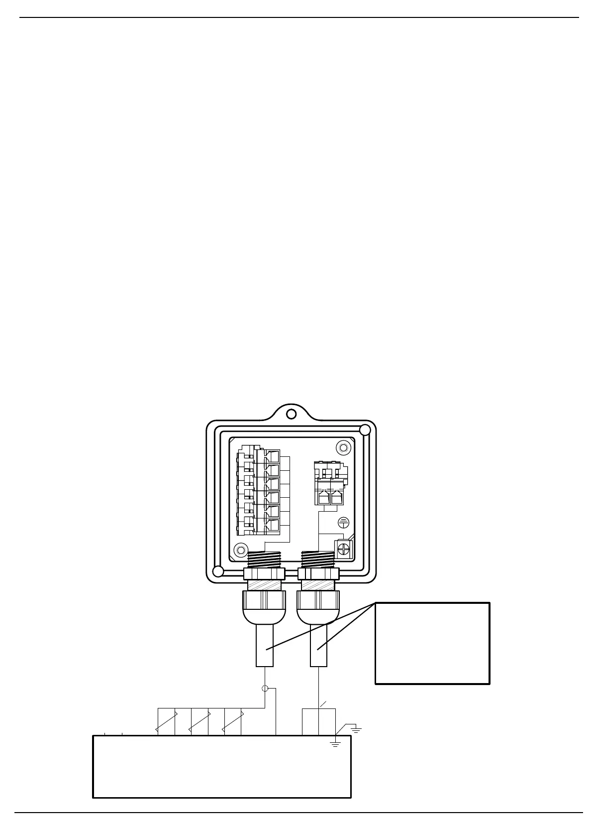
A nschluss-S chem a
6-adriges abgeschirm tes Kabel. A dern m öglichst
p a a r w e is e v e rd rillt. A b s c h irm u n g a n K le m m e G N D
des R P O ... . A bschirm ung nicht m it S chutzleiter
oder M verbinden!
A nschlusskabel z.B .:
L ifY C Y 6 x 2 x 0 ,2 0 / 2 2 o d e r
LiYC Y 6 x 2 x 0,20
B 1 ( + ) S ig n a l O
2
-M esszelle
M (-) M a s s e fü r B 1 , B 2
B2 (+) Therm oelem ent-Spannung
M (-)
U 3 (+) Signal Tem peraturkom pensations-
element
G 2 (-) S peisung Tem peraturkom pensations-
element
G N D M asse für A nschirm ung
3 x 1,5 m m :
Q 4 Fühlerheizung (A C 230 V)
Q 5 Fühlerheizung (A C 230 V)
A E rde*
8
Vorsicht b e i d e n A n s c h lü s s e n U 3 u n d G 2 !
Ein Fehlverdrahten der Anschlüsse führt zu einem
A usfall des K om pensationselem entes.
* A m R P O ... s te h t n u r 1 E rd le ite rk le m m e z u r
V e rfü g u n g . B e id e E rd le ite r m ü s s e n a u f eine
K lem m e geführt w erden.
2
Schém a de raccordem ent
C â b le b lin d é à 6 b rin s . B rin s to rs a d é s s i p o s s ib le p a r
p a ire s . B lin d a g e s u r la b o rn e G N D d u R P O ... . N e p a s
connecter le blindage avec le conducteur de protection
ou M !
C âble de raccordem ent p.ex.:
L ifY C Y 6 x 2 x 0 ,2 0 / 2 2 o u
LiYC Y 6 x 2 x 0,20
B 1 ( + ) S ig n a l d e la c e llu le d e m e s u re d ´O
2
M (-) M a s s e p o u r B 1 , B 2
B2 (+) Tension de therm ocouple
M (-)
U 3 (+) Signal de l´élém ent de cpm pensation de
tem pérature
G 2 (-) A lim entation de l´élém ent de
com pensation de tem pérature
G N D M asse du blindage
3 x 1,5 m m :
Q 4 C hauffage de sonde Q G O ... (A C 230 V)
Q 5 C hauffage de sonde Q G O ... (A C 230 V)
A Terre*
8
P rière de faire attention lors des raccordem ents U 3
et G 2. U ne erreur de câblage des fils de raccor-
dem ent conduit à une destruction de l´élém ent de
com pensation.
* Le R PO ... ne dispose que d´une seule borne de
m is e à la te rrre . L e s d e u x fils d e m is e à la te rre
doivent être connectés sur la m ê m e borne.
2
W ir in g d ia g r a m
Shielded 6-core cable. W ires should be tw isted in
p a irs . S c re e n m u s t b e c o n n e c te d to te rm in a l G N D
o f th e R P O ... . D o n o t c o n n e c t th e s h ie ld in g to th e
protective earth or M !
C onnecting cable e.g.:
L ifY C Y 6 x 2 x 0 ,2 0 / 2 2 o r
LiYC Y 6 x 2 x 0,20
B 1 (+ ) S ig n a l fro m O
2
-m e a s u rin g c e ll
M (-) G ro u n d fo r B 1 , B 2
B2 (+) Therm ocouple voltage
M (-)
U 3 (+ ) S ig n a l fro m te m p e ra tu e
com pensation elem ent
G 2 (-) P ow er supply for tem perature
com pensation elem ent
G N D G round for screening
3 x 1,5 m m :
Q 4 Q G O ... detector heating (AC 230 V )
Q 5 Q G O ... detector heating (AC 230 V )
A Earth*
8
Caution w hen connecting U 3 and G 2!
F a u lty w irin g le a d s to fa ilu re o f th e c o m p e n s a tio n
elem ent.
* A t th e R P O ..., th e re is o n ly 1 e a rth te rm in a l
available. B oth earth w ires m ust be connected
to the sam e e a rth te rm in a l.
2


 To Next Page