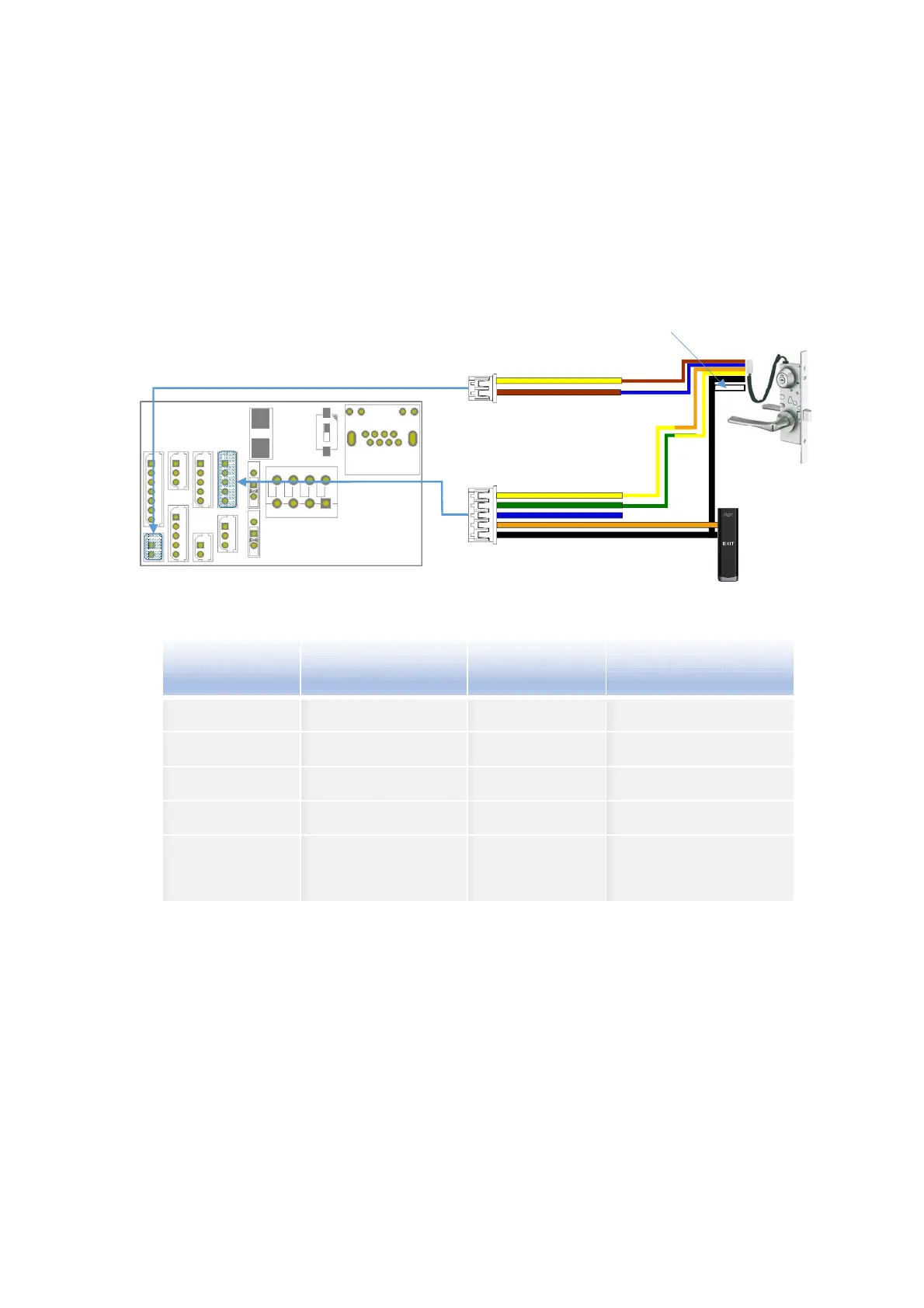
Motor Lock
* After checking the motor lock operating voltage, change the input voltage to 24V if
necessary.
** In case of Japanese locks, 24V locks are often used, so you need to be careful.
* In case of motor lock, it is necessary to connect the lock state input correctly to prevent
malfunction.
Function
UBio-X Face Premium
(Wire Color)
Motor Lock
(Wire Color)
Remark
Motor + YELLOW BROWN
Motor - BROWN BLUE
Door Monitor 0 YELLOW ORANGE Door State(NO)
Door Monitor 1 GREEN YELLOW Lock State(NC)
Ground BLACK BLACK
WHITE
Black & White wire
connect together
of the motor
EB-030
Exit button
4/EXIT
1/DM0
5/GND
1/Motor +/Yellow
Motor Lock
U9AL3MHD
(DC24/0.3A)
2/Motor -/Brown
2/DM1
The white wire of the motor is connected
with the black wire
UBio-X Face Premium
** The color may be different depending on the lock, so please refer to the lock’s
user manual.
22
 Loading...