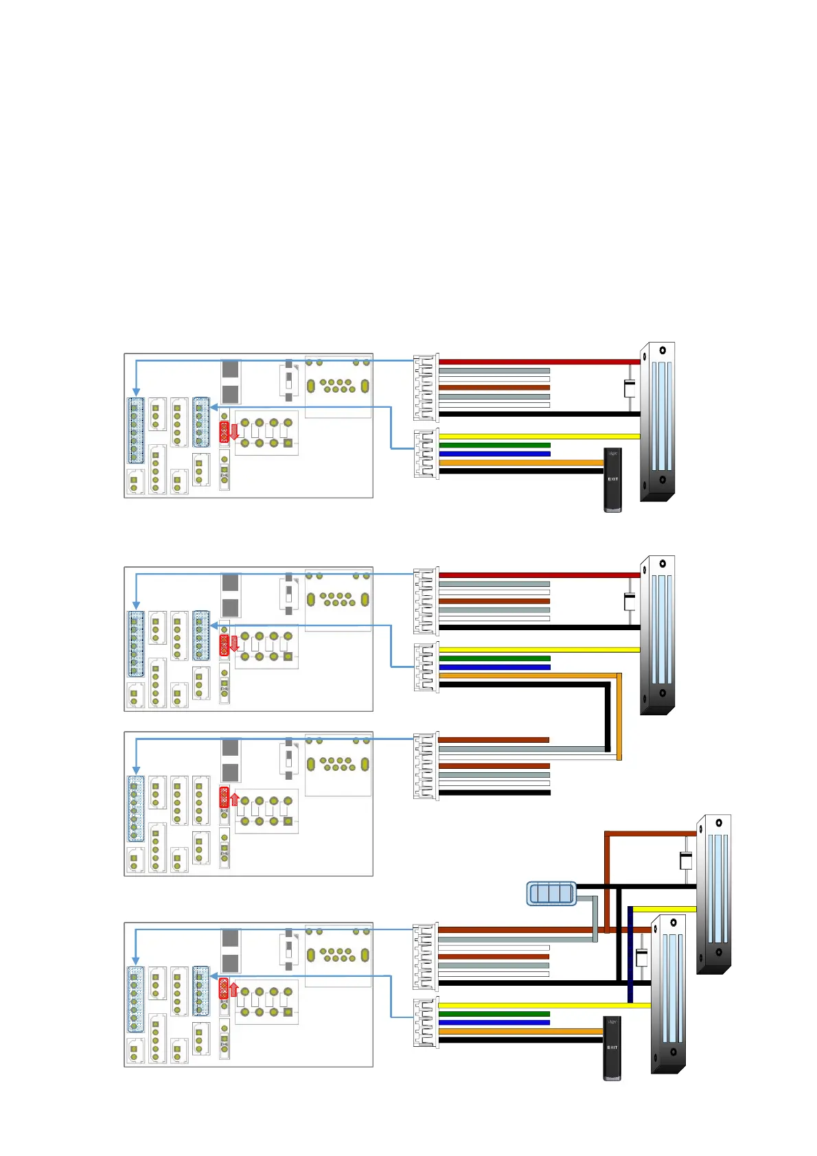
Lock Connection
Fail Safe Lock
* Fail Safe Lock opens when the power of the product is cut off due to a power failure, etc.
* When the lock is locked, power is supplied to the lock, and when the power supplied to the
lock is cut off by the door opening control operation, the door is opened.
* The basic connection method is the same for the Deadbolt Lock, Strike Lock, EM Lock.
* If 24V lock is required while supplying power for lock operation from the product, change the
product’s power supply to a 24V adapter.
* Apply power after completing all wiring.
* In order to protect the product from the counter electromotive force generated during lock
operation, connect the diode at a location close to the lock as shown in the figure with the
correct polarity.
One system, one Lock connection/ Door state input & Exit button
* SW4 On position
EB-030
Exit button
Lock
4/EXIT
1/L1NC
7/GND
1/DM0
5/GND
(+)
(-)
UBio-X Face Premium
Two system, one Lock Connection/ Door state input
* SW4 On position
* SW4 Off position
System 1
System 2
Lock
4/EXIT
1 L1NC
7/GND
1/DM0
5/GND
2/L1C
3/L1NO
(+)
(-)
One system, two Lock connection/ Door state input & Exit button
* SW4 Off position
EB-030
Exit button
Lock 1
4/EXIT
1/L1NC
7/GND
1/DM0
5/GND
12V or 24V
Adapter
2/ L1C
(-)
(+)
(+)
Lock 2
(-)
19
 Loading...