Page 34
POWERING TECHNOLOGY
Manual No. MS0027-MAN rev. 4
guardian_access_3u_ms27-man-rev4-0817.indd
XC3
3
2
1
Alarm 1
6
5
4
Alarm 2
XC6
3
2
1
Alarm 3
6
5
4
Alarm 4
XC5
2
1
Multi purpose 7-12
Multi purpose 1-6
XC2
+5V
0V
TEMP1(BATT)
3
2
1
XC4
50
XC1
Digital In 2
+5V
Digital In 1
XC7
Digital out 2
+VR
Digital out 1
XC8
+5V
0V
TEMP2(AMB)
6
5
4
4
3
6
5
8
7
10
9
12
11
1
2
3
4
5
6
1
2
3
4
5
6
1
2
3
4
5
6
K1
K2
K4
K3
K5
K6
XC10
XC9
XC11
GND
GND
Symmetry#1
Symmetry#2
Temperature
sensor
Red
Green
Blue
Red
Green
Red
Green
Blue
8
8
XC13
XC12
Temperature
sensor
Red
Green
Blue
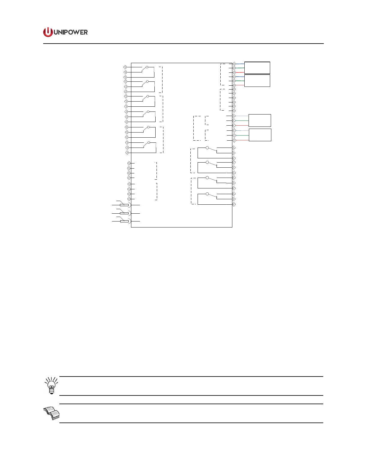
Figure 4-15 ACC Relay Board
The alarm interface board is located in the top right side of the system. To connect the alarm
cable to the alarm interface board, follow the steps below:
1. Remove the green plug from each connector.
2. Determine whether to reference normally closed or normally open with reference to
common for each alarm contact.
3. Strip the wires back approximately 10mm. Stranded wire may be soldered or covered
with copper ferrule if desired.
4. Insert the wire into the top openings of the green plug and tighten the screw to clamp
wire.
5. Re-insert the green plug with the alarm cable into the alarm interface board.
NOTE The alarm conguration will be dependent on your system conguration.
NEED MORE INFORMATION? For detailed information regarding Alarm connection
see Appendix A, Installation Drawing.

 Loading...