The UNIRAC ULA (Planning and Assembly) system is a code-compliant installation manual for solar PV arrays, designed to provide a robust and secure mounting solution for various module types and installation environments. This system is suitable for both landscape and portrait array configurations, with portrait arrays utilizing the same components as landscape arrays. The manual emphasizes compliance with local and national building codes, ensuring that installers are responsible for safe and appropriate installations.
Function Description:
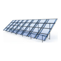
The UNIRAC ULA system serves as a ground-mount racking solution for photovoltaic modules. It is designed to facilitate the secure and efficient installation of solar panels, providing structural support, bonding, and grounding paths for the entire PV array. The system's components are engineered to create a stable and durable framework that can withstand environmental loads and ensure the long-term performance of the solar installation.
Key functions include:
- Module Mounting: Provides various clamp types (Standard Series, Pro Series, Universal AF) to securely attach solar modules to the rails, accommodating different module thicknesses and ensuring proper spacing.
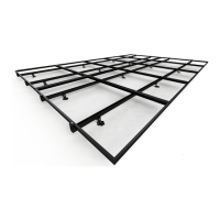
- Structural Support: Utilizes a combination of rails, caps, sliders, rail brackets, cross braces, and vertical/horizontal pipes to form a rigid structure that supports the modules at an optimal tilt angle.
- Bonding and Grounding: Incorporates integrated bonding features within clamps and dedicated grounding lugs (WEEBLug, ILSCO Lug) to establish continuous electrical bonding between modules, rails, and the overall grounding system, complying with NEC 70 requirements.
- Foundation Integration: Designed to work with concrete foundations, where vertical pipes are embedded to provide stable support for the array structure. Ground screw installation is also an option.
- Assembly Flexibility: Offers options for assembly sequences, allowing installers to choose between pre-assembling the full truss structure or installing vertical leg pipes and pouring concrete first, depending on the project size and preference.
Important Technical Specifications:
- Material Specifications:
- Rails, caps, sliders, rail brackets, cross braces, bottom mounting clips, and top mounting clamps: Made from 6105-T5 aluminum extrusion. Caps are welded for enhanced durability.
- Fasteners: Constructed from 304 stainless steel, ensuring corrosion resistance and strength.
- Horizontal and vertical pipe (installer supplied): Minimum requirement is 2” ASTM A53B Schedule 40 galvanized steel pipe.
- Concrete (installer supplied): Rated for a minimum of 2,500 pounds per square inch.
- Module Mounting Clamp Specifications:
- Standard Series Clamps: Secure modules with a 0.25" gap between modules.
- Pro Series Clamps: Secure modules with a 1" gap between modules.
- Universal AF Clamps: Secure modules with a 0.5" gap between modules.
- Supported Module Thicknesses (for various endclamp types):
- B: 30MM-32MM
- C: 33MM-36MM
- D: 38MM-40MM
- K: 39MM-41MM
- F: 45MM-47MM
- E: 50MM-51MM
- Torque Values:
- Set screws for leg caps and sliders: 15 foot-pounds.
- 3/8-inch serrated flange nuts for U-bolts and rail brackets: 8 foot-pounds.
- 1/4-inch module mounting hardware: 10 foot-pounds (with Anti-Seize).
- WEEBLug conductor (6-14 AWG): 5 ft-lbs.
- WEEBLug (overall assembly): 10 ft-lbs.
- ILSCO Lay-in Lug conductor: 4-6 AWG: 35 in-lbs; 8 AWG: 25 in-lbs; 10-14 AWG: 20 in-lbs.
- ILSCO Lay-in Lug (overall assembly): 5 ft-lbs.
- Pro Series Endclamp bolt: 5 ft-lbs (No anti-seize).
- Universal AF Endclamp bolt: 15 ft-lbs.
- Grounding:
- Minimum 10 AWG, 105°C Copper Wire for fault current ground path.
- Maximum over current protection device (OCPD) of 30A.
- Certification: UL2703 listed for rack mounting systems and clamping devices for flat-plate photovoltaic modules and panels. Includes standard electrical grounding, electrical bonding, and mechanical load testing.
- System Fire Class Rating and Design Load Rating: See installation instructions for specific requirements.
- Certification marking is embossed on all mid clamps.
Usage Features:
- Detailed Planning: Emphasizes the importance of consulting engineered plans for North-South and East-West foundation spacing, brace configurations, and module/rail layouts to avoid conflicts.
- Foundation Preparation: Provides clear instructions for digging foundation holes to specified diameters and depths, ensuring footings extend below the frost line. It also addresses scenarios with shallow groundwater.
- Vertical Pipe Installation: Guides installers on preparing vertical pipes with rebar, threaded caps, or bolts to prevent withdrawal from the footing, and how to position and level them before pouring concrete.
- Assembly Sequence Options: Allows flexibility in assembly, enabling installers to either pre-assemble the truss structure for smaller arrays or install vertical pipes first for larger installations.
- Module Layout Planning: Instructs installers to plan and mark bracket, rail, and module locations on horizontal pipes to resolve potential conflicts with caps.
- Microinverter Mounting: Provides a step-by-step guide for installing microinverter mount T-bolts and microinverters onto the rails, including torque specifications and position indicator verification.
- System Grounding: Offers detailed instructions for installing WEEBLug and ILSCO Lay-in Lug conductors, including bolt sizes, drill sizes, and torque values. It highlights the importance of isolating copper from aluminum to prevent corrosion.
- Clamp Installation: Provides specific instructions for installing Standard Series, Pro Series, and Universal AF endclamps and midclamps, including T-bolt insertion, rotation, and torque values. It also details how to engage module frames with clamps and ensure proper alignment.
- Module Placement: Guides installers on positioning modules, ensuring proper engagement with clamps and maintaining specified gaps between modules.
- Pre-fabrication Option: Notes that North-South columns of modules can be pre-fabricated, mounted to rails, and wired off-site before being lifted into position, potentially saving time.
- Code Compliance: The system is designed to be code-compliant, with certification marking labels provided for application to the rail at the edge of the array.
Maintenance Features:
- Periodic Inspection: The manual recommends conducting periodic inspections of the UNIRAC ULA system.
- Checks for Loose Components: Installers and system owners should regularly check for any loose components within the array structure.
- Fastener Integrity: Inspections should include verifying the tightness of all fasteners to ensure they remain at their specified torque values.
- Corrosion Monitoring: The system components should be checked for any signs of corrosion, especially at connection points and where different metals meet.
- Damage Assessment: Any components showing signs of damage that could compromise the safety or structural integrity of the array must be identified.
- Replacement of Damaged Parts: The manual explicitly states that any components found to be damaged to the extent of compromising safety shall be replaced immediately. This ensures the continued safe and reliable operation of the PV array.