ULA
PLANNING AND
ASSEMBLY
INSTALLATION MANUAL
INSTALLATION GUIDE
PAGE
1
IMAGE-1-LANDSCAPE ASSY
IMAGE-2-FRONT CAP
IMAGE-3-REAR CAP
IMAGE-4-SLIDER
IMAGE-5-OPTIONAL CROSS BRACE
IMAGE-6-RAIL BRACKET
IMAGE-7-SM OR GFT RAIL
1
1
2
2
3
3
4
4
5
5
6
6
7
7
8
8
A A
B B
C C
D D
6
6
1
1
1
2
2
2
3
3
3
4
4
4
5
5
5
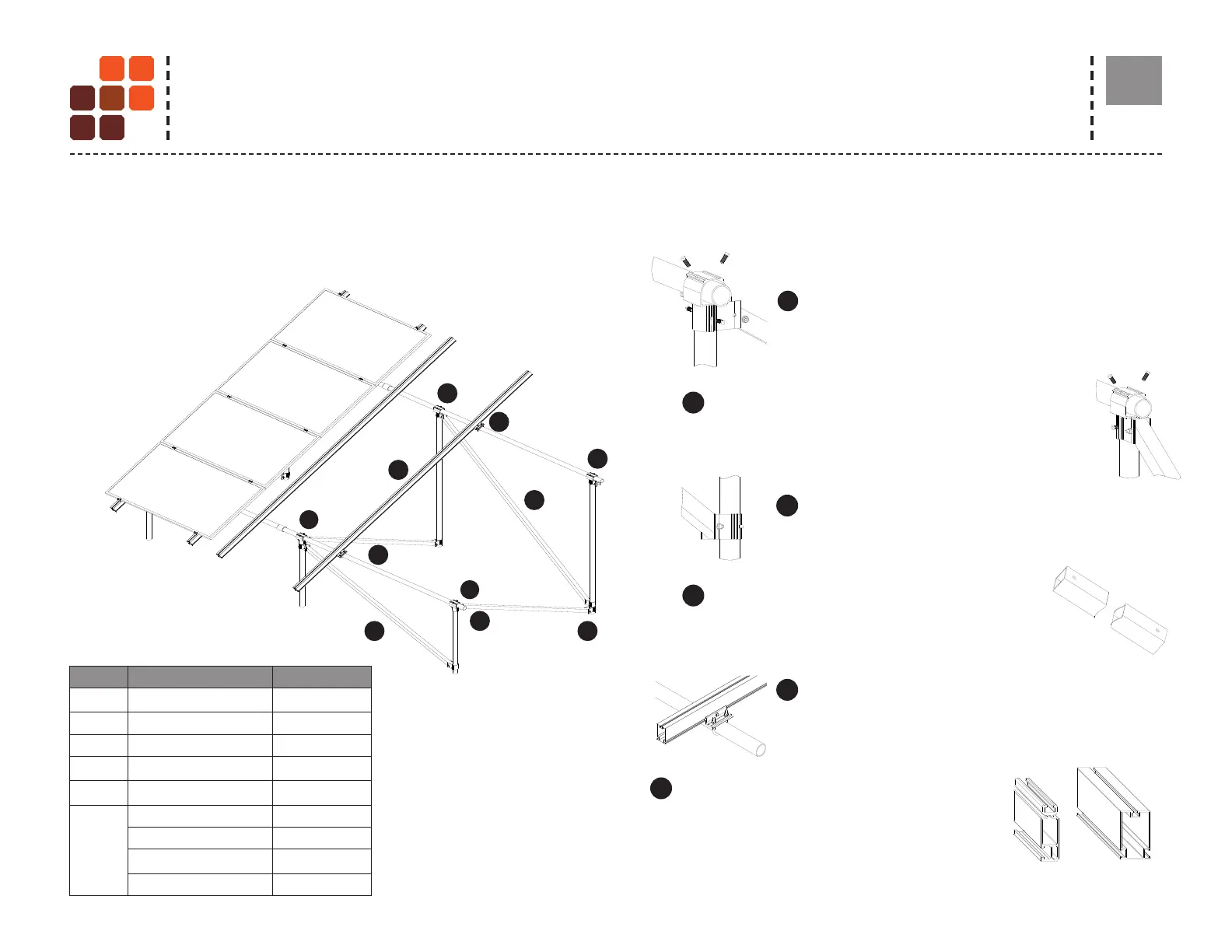
Note: Incidental materials such as temporary bracing or gravel may be necessary.
Note:
East-West Cross Braces must be
installed in pairs with a rear and
a front brace connected to the
same vertical pipe bay.
• Brace pairs can be installed
on any leg pair in the array.
• Bonding Clamps are Single
use only.
Rear cap: Attaches back horizontal pipe and upper
end of East-West braces to vertical pipes . Included
hardware: (2) U-bolts, (4) ange nuts, set screws.
Optional Cross Brace: Provides North-South and
East-West diagonal bracing. *See design guide or
U-Builder
Front cap: Attaches front horizontal pipe and upper
end of North-South braces to vertical pipe. Included
hardware: (2) U-bolts, cross-brace bolt, (5) ange nuts,
set screws.
Slider: Attaches lower end of North-South cross brace
and both ends of East-West braces to vertical pipes.
Included Hardware: (1) cross-brace bolt, (1) ange nut,
set screws.
Rail Bracket: Attaches rail to horizontal pipes.
Included hardware: (1) U-bolt, (1) 1/2 inch bolt, and
(2) ange nuts.
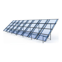
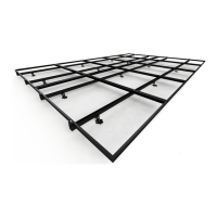
SOLARMOUNT OR GFT Rails:
SM Standard or GFT rails support PV modules.
Components and quantities specic to your installations are listed on your quotation.
ULA COMPONENTS
IMAGE-1-LANDSCAPE ASSY
IMAGE-2-FRONT CAP
IMAGE-3-REAR CAP
IMAGE-4-SLIDER
IMAGE-5-OPTIONAL CROSS BRACE
IMAGE-6-RAIL BRACKET
IMAGE-7-SM OR GFT RAIL
1
1
2
2
3
3
4
4
5
5
6
6
7
7
8
8
A A
B B
C C
D D
IMAGE-1-LANDSCAPE ASSY
IMAGE-2-FRONT CAP
IMAGE-3-REAR CAP
IMAGE-4-SLIDER
IMAGE-5-OPTIONAL CROSS BRACE
IMAGE-6-RAIL BRACKET
IMAGE-7-SM OR GFT RAIL
1
1
2
2
3
3
4
4
5
5
6
6
7
7
8
8
A A
B B
C C
D D
IMAGE-1-LANDSCAPE ASSY
IMAGE-2-FRONT CAP
IMAGE-3-REAR CAP
IMAGE-4-SLIDER
IMAGE-5-OPTIONAL CROSS BRACE
IMAGE-6-RAIL BRACKET
IMAGE-7-SM OR GFT RAIL
1
1
2
2
3
3
4
4
5
5
6
6
7
7
8
8
A A
B B
C C
D D
IMAGE-1-LANDSCAPE ASSY
IMAGE-2-FRONT CAP
IMAGE-3-REAR CAP
IMAGE-4-SLIDER
IMAGE-5-OPTIONAL CROSS BRACE
IMAGE-6-RAIL BRACKET
IMAGE-7-SM OR GFT RAIL
1
1
2
2
3
3
4
4
5
5
6
6
7
7
8
8
A A
B B
C C
D D
IMAGE-1-LANDSCAPE ASSY
IMAGE-2-FRONT CAP
IMAGE-3-REAR CAP
IMAGE-4-SLIDER
IMAGE-5-OPTIONAL CROSS BRACE
IMAGE-6-RAIL BRACKET
IMAGE-7-SM OR GFT RAIL
1
1
2
2
3
3
4
4
5
5
6
6
7
7
8
8
A A
B B
C C
D D
IMAGE-1-LANDSCAPE ASSY
IMAGE-2-FRONT CAP
IMAGE-3-REAR CAP
IMAGE-4-SLIDER
IMAGE-5-OPTIONAL CROSS BRACE
IMAGE-6-RAIL BRACKET
IMAGE-7-SM OR GFT RAIL
1
1
2
2
3
3
4
4
5
5
6
6
7
7
8
8
A A
B B
C C
D D
S.NO. PART PART NUMBER
1
Front cap 403211C
2 Rear cap 403214C
3 Slider 403215C
4
Optional Cross Brace 403200C
5
Rail Bracket 403216M
6
SM Rail CLR 310xxxC
SM Rail DRK 310xxxD
SM Rail MILL 320xxxM
GFT Rail 411166M
SYSTEM COMPONENTS