ULA
PLANNING AND
ASSEMBLY
INSTALLATION MANUAL
INSTALLATION GUIDE
PAGE
4
FOUNDATIONS
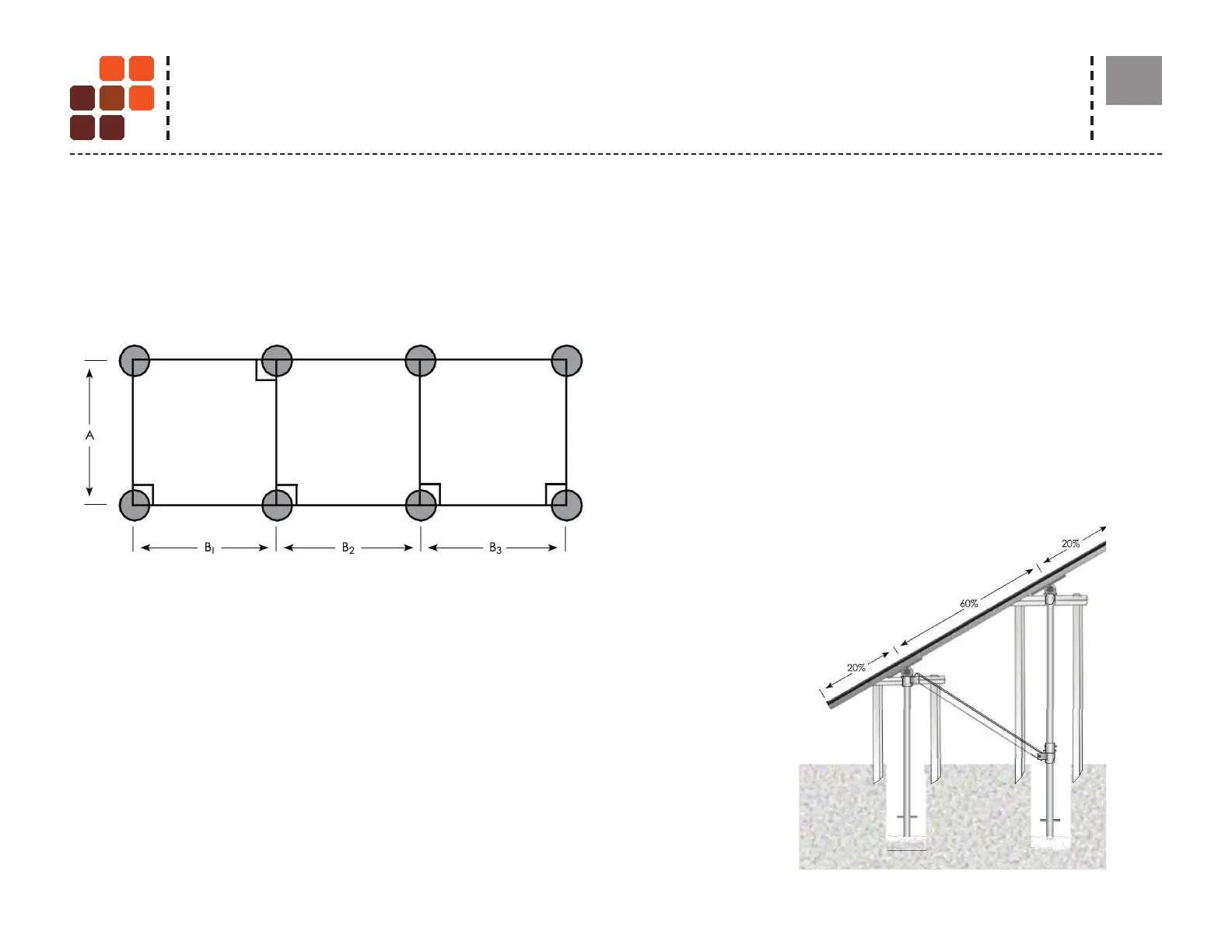
Lay out and excavate leg positions
Consult the engineered plans to determine the North-South and East-West
foundation spacing. Establish a grid and mark the foundation locations. Verify that
all angles are square as shown in gure 1.
*Visit unirac.com/technical-support/ for more information on Ground Screw installation.
SELECT AN ASSEMBLY SEQUENCE
Figure - 1 North-South leg spacing (A) is fi xed. East-West spacing (B₁, B₂, etc.) is
identical in most installations, see "Average leg spacing E-W " (Nominal Values under
"Design parameters") on page 2 of your Specs Sheet. However, if you needed to shift
leg positions, follow the east - west spacing you set during your planning session.
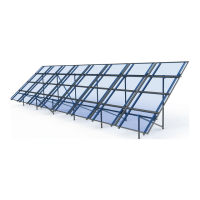
The assembly sequence depends on installer preference and the size
of the installation. Either of these options may be followed:
• If a ULA has just a few pairs (up to 3 pairs) of legs, installers
may prefer to assemble the full truss structure prior to pouring
concrete. See gure 2
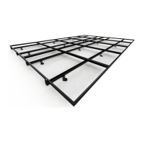
• On the larger ULA structures with many pairs (more than 3 pairs)
of legs, installers prefer to place the vertical leg pipes, pour the
concrete, and let it cure overnight before installing. See gure 5.
Note: In either case, when mounting rails, be sure to center them on
the horizontal pipes, which will leave about 20 percent overhang on
north and south sides.
Figure 2
SYSTEM LAYOUT