ULA
PLANNING AND
ASSEMBLY
INSTALLATION MANUAL
INSTALLATION GUIDE
PAGE
7
ASSEMBLY
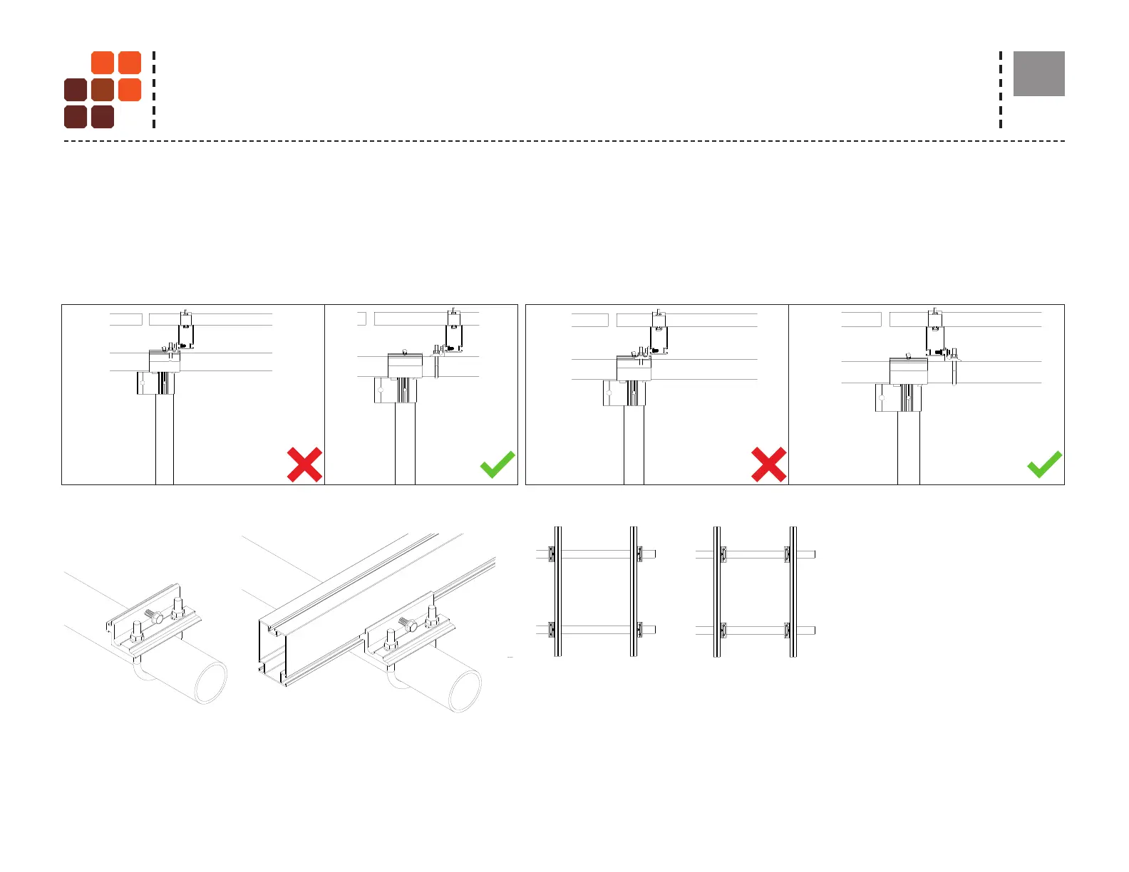
Plan Bracket, Rail & Clamp Layout
Before installing rails, plan the layout and locations of Brackets, Rails and Modules to identify and resolve any conicts with Front and Rear Caps. Measure and
mark each module column on the horizontal pipe. Then, mark bracket and rail locations.
If a conict is discovered, resolve it by using one or both of the methods shown below.
Install the bracket onto a top rail and torque it.
TORQUE VALUE
3/8" Serrated ange nut for U-Bolt to 8 ft-lbs
Center the rail over the horizontal pipes with
overhangs on North and South sides of the array.
Secure the rail onto the bracket with the provided
hardware by torquing the self threading bolt until
it punctures and is snug to the rail.
Above images show the different Install
orientations for Rail Bracket on rail.
NOTE:
1. If desired, North-South columns
of modules can be pre-fabricated,
mounted to rails and wired on
the ground, or even off site, then
lifted into position and secured
to the horizontal pipes.
2. Please see design guide or
U-Builder for guidance on rail
type and bracket quantity.
Solution-1 Shift rail & bracket east-west Solution-2 Flip bracket connection to another slot
IMAGE-1-CONFLICT-1
IMAGE-2-SOLUTION-SHIFT BRACKET EW
IMAGE-3-CONFLICT-1
1
1
2
2
3
3
4
4
5
5
6
6
7
7
8
8
A A
B B
C C
D D
IMAGE-1-CONFLICT-1
IMAGE-2-SOLUTION-SHIFT BRACKET EW
IMAGE-3-CONFLICT-1
IMAGE-4-SOLUTION-FLIP THE BRACKET TO THE OPPOSITE SIDE
1
1
2
2
3
3
4
4
5
5
6
6
7
7
8
8
A A
B B
C C
D D
IMAGE-1-CONFLICT-1
1
1
2
2
3
3
4
4
5
5
6
6
7
7
8
8
A A
B B
C C
D D
IMAGE-1-CONFLICT-1
IMAGE-2-SOLUTION-SHIFT BRACKET EW
1
1
2
2
3
3
4
4
5
5
6
6
7
7
8
8
A A
B B
C C
D D
IMAGE-1-CONFLICT-1
IMAGE-2-SOLUTION-SHIFT BRACKET EW
IMAGE-3-CONFLICT-1
IMAGE-4-SOLUTION-FLIP THE BRACKET TO THE OPPOSITE SIDE
IMAGE-8-ALTERNATE RAIL BRACKET ORIENTATION
IMAGE-7-RAIL BRACKET INSTALL
IMAGE-5 BRACKET INSTALL
1
1
2
2
3
3
4
4
5
5
6
6
7
7
8
8
A A
B B
C C
D D
IMAGE-1-CONFLICT-1
IMAGE-2-SOLUTION-SHIFT BRACKET EW
IMAGE-3-CONFLICT-1
IMAGE-4-SOLUTION-FLIP THE BRACKET TO THE OPPOSITE SIDE
IMAGE-7-ALTERNATE RAIL BRACKET ORIENTATION
IMAGE-6-RAIL BRACKET INSTALL
IMAGE-5 BRACKET INSTALL
1
1
2
2
3
3
4
4
5
5
6
6
7
7
8
8
A A
B B
C C
D D
IMAGE-1-CONFLICT-1
IMAGE-2-SOLUTION-SHIFT BRACKET EW
IMAGE-3-CONFLICT-1
IMAGE-4-SOLUTION-FLIP THE BRACKET TO THE OPPOSITE SIDE
IMAGE-8-ALTERNATE RAIL BRACKET ORIENTATION
IMAGE-7-RAIL BRACKET INSTALL
IMAGE-5 BRACKET INSTALL
IMAGE-6 BRACKET INSTALL ON RAIL
1
1
2
2
3
3
4
4
5
5
6
6
7
7
8
8
A A
B B
C C
D D
IMAGE-1-CONFLICT-1
IMAGE-2-SOLUTION-SHIFT BRACKET EW
IMAGE-3-CONFLICT-1
IMAGE-4-SOLUTION-FLIP THE BRACKET TO THE OPPOSITE SIDE
IMAGE-8-ALTERNATE RAIL BRACKET ORIENTATION
IMAGE-7-RAIL BRACKET INSTALL
IMAGE-5 BRACKET INSTALL
1
1
2
2
3
3
4
4
5
5
6
6
7
7
8
8
A A
B B
C C
D D
SYSTEM ASSEMBLY