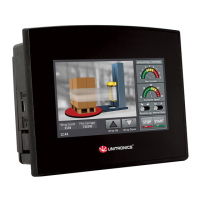
Samba™ OPLC™
Unitronics 11
SM35-J-R20/SM35-J-T20
This series comprises a build-in RS232 port.
Caution
Signals are related to the controller’s 0V; the same 0V is used by the power supply.
The serial port is not isolated. If the controller is used with a non-isolated external device,
avoid potential voltage that exceeds ± 10V.
Use RS232 to download programs from a PC, and to communicate with serial devices and
applications, such as SCADA.
Pinouts
The pinouts below show the PLC port signals.
RS232
Pin # Description
1 Not connected
2 0V reference
3 TXD signal
4 RXD signal
5 0V reference
6 Not connected
Opening the Controller
Before performing these actions, touch a grounded object to discharge any electrostatic charge.
Avoid touching the PCB board directly. Hold the PCB board by its connectors.
1. Turn off the power supply, disconnects, and dismounts the controller.
2. The back cover of the controller comprises 4 screws, located in the corners.
Remove the screws, and pull off the back cover.
Changing I/O Settings
The I/O board of the controller is now
exposed, enabling you to change
I/O settings (module dependent) according to
the jumpers setting above.
Note: Photo is for illustration purposes only.
(Using SM70)
Closing the Controller
Replace the back cover of the controller and fasten the corner screws.
Note that you must replace the back cover securely before powering up the controller.
 Loading...