UMI-B1 UL Series Inverter Installation guide
16
3.2.3 Wiring of terminals in main circuit
1. Connect the ground line of input power cable to the ground terminal of inverter (PE)
directly, and connect 3PH input cable to R, S and T and fasten up.
2. Connect the ground line of motor cable to the ground terminal of the inverter, and
connect the 3PH motor cable to U, V, W and fasten up.
3. Connect the brake resistor which carries cables to the designated position.
4. Fasten up all the cables on the outside of the inverter if allowed.
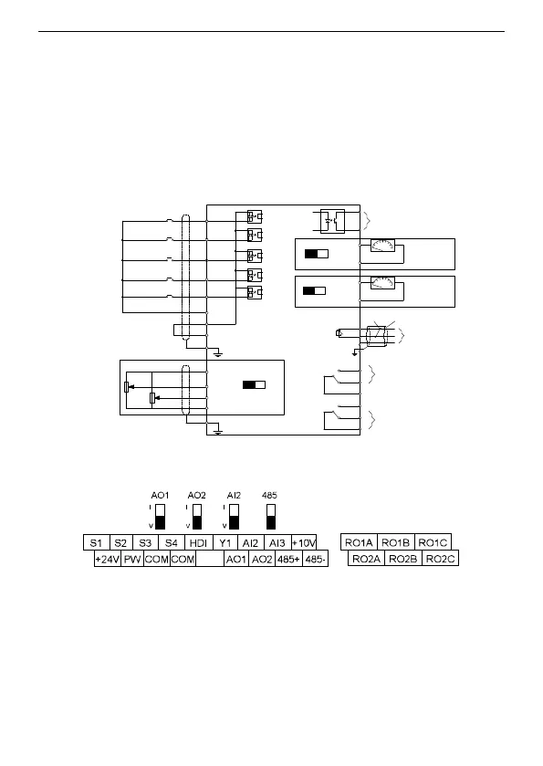
3.2.4 Wiring diagram of control circuit
Multi-function input terminal 1
Multi-function input terminal 2
Multi-function input terminal 4
High speed pulse input collector
Multi-function input terminal 3
Open collector input optional
Y1 output
Analog output
Analog output
Relay 1 output
Relay 2 output
S1
S2
S3
S4
HDI
COM
PW
+24V
PE
+10V
AI2
AI3
PE
GND
AI2
V I
Y1
COM
AO1
AO2
V I
V
I
AO1
AO2
0–10V/0–20mA
0–10V/0–20mA
COM
COM
RO1A
RO1B
RO1C
RO2A
RO2B
RO2C
Shield layer
Twisted pair
RS485
communication
485+
485-
GND
PE
J5
Figure 3-6 Wiring of control circuit
3.2.5 Terminals of control circuit
Figure 3-7 Terminals of control circuit
 Loading...