UMI-B1 UL Series Inverter Installation guide
17
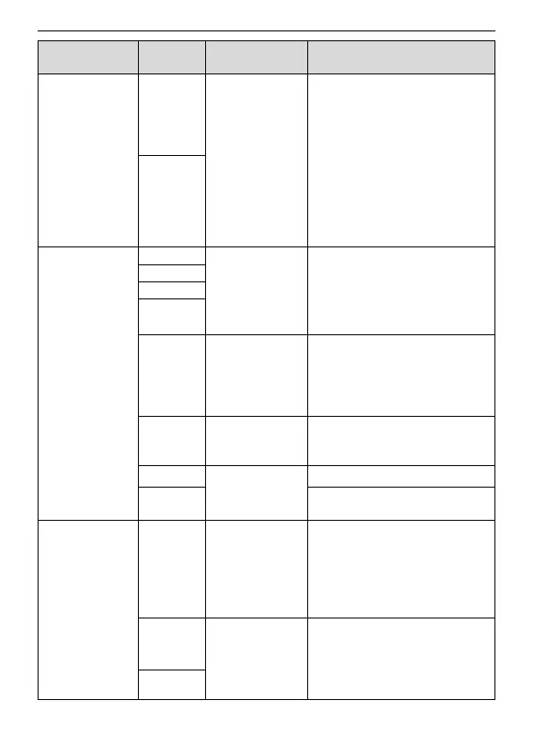
RS485 communication interface.
In order to ensure stable
communication channel:
• Use shielded twisted pair
cable.
• Connect the HOST RS485
signal ground to one of the
VFD CMD/GND terminals.
• Connect one of the CMD/GND
terminals to PE terminal.
• Earth the cable shield to the
PE terminal.
1. Internal impedance: 3.3kΩ
2. 12–30V voltage input is
available
3. The terminal is the
dual-direction input terminal
4. Max. input frequency: 1kHz
High frequency
input channel
Except for S1–S4, this terminal
can be used as high frequency
input channel.
Max. inputfrequency: 50kHz
Duty cycle: 30%–70%
To provide the external digital
power supply
Voltage range: 12–30V
Contact capacity: 50mA/30V
Common terminal of the open
collector output
External 10V
reference
power supply
10V reference power supply
Max. output current: 50mA
As the adjusting power supply of
the external potentiometer
Potentiometer resistance: 5kΩ
above
1. Input range: AI2 voltage and
current can be chosen:
0–10V/0–20mA; AI3:
-10V–+10V.
2. Input impedance:voltage
 Loading...