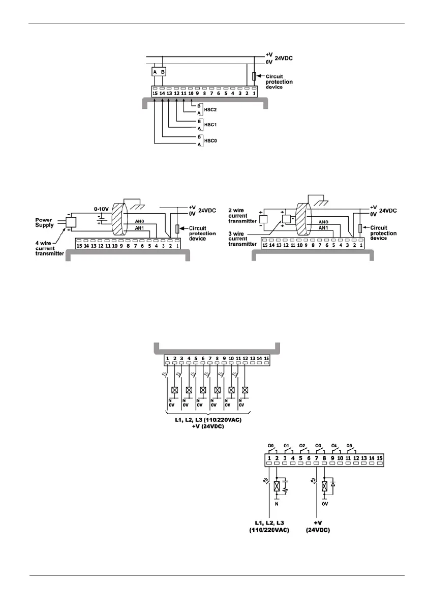
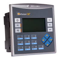
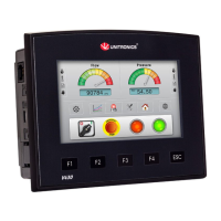
EasyManuals Logo

Unitronics V130-33-TR20 User Manual

Unitronics V130-33-TR20
10 pages
To Next Page IconTo Next Page
To Previous Page IconTo Previous Page
Page #7 background imageLoading...
Page #7 background image
Vision™ OPLC™
Unitronics
7
Shaft-encoder
Analog Input Wiring
Analog input wiring, current/voltage (4-wire)
Analog input wiring, current (2/3 wire)
Shields should be connected at the signal’s source.
The 0V signal of the analog input must be connected to the controller’s 0V.
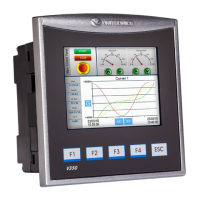
Relay Outputs
Increasing Contact Life Span
To increase the life span of the relay output contacts
and protect the device from potential damage by
reverse EMF, connect:
A clamping diode in parallel with each inductive
DC load
An RC snubber circuit in parallel with each
inductive AC load
i4 Automation Ltd - 01480 395256

Questions and Answers:

Question and Answer IconNeed help?

Do you have a question about the Unitronics V130-33-TR20 and is the answer not in the manual?

Unitronics V130-33-TR20 Specifications

General IconGeneral
BrandUnitronics
ModelV130-33-TR20
CategoryNetwork Router
LanguageEnglish

Related product manuals