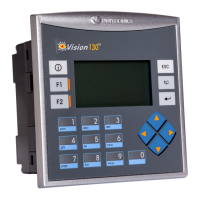
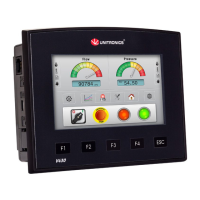
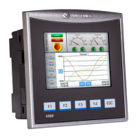
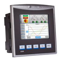
Vision™ OPLC™
Unitronics 5
Wiring
Do not touch live wires.
Install an external circuit breaker. Guard against short-circuiting in external wiring.
Use appropriate circuit protection devices.
Unused pins should not be connected. Ignoring this directive may damage the device.
Double-check all wiring before turning on the power supply.
Caution
To avoid damaging the wire, do not exceed a maximum torque of 0.5 N·m (5 kgf·cm).
Do not use tin, solder, or any substance on stripped wire that might cause the wire
strand to break.
Install at maximum distance from high-voltage cables and power equipment.
Wiring Procedure
Use crimp terminals for wiring; use 3.31 mm ² –0.13 mm² wire (12-16 AWG):
1. Strip the wire to a length of 7±0.5mm (0.270–0.300“).
2. Unscrew the terminal to its widest position before inserting a wire.
3. Insert the wire completely into the terminal to ensure a proper connection.
4. Tighten enough to keep the wire from pulling free.
Input or output cables should not be run through the same multi-core cable or share
the same wire.
Allow for voltage drop and noise interference with I/O lines used over an extended distance.
Use wire that is properly sized for the load.
The controller and I/O signals must be connected to the same 0V signal.
I/Os
V130/V350/V130J/V350J/V430J-RA22 models comprise a total of 12 inputs, 8 relay outputs and
2 analog outputs.
V130/V350/V130J/V350J/V430J-TRA22 models comprise a total of 12 inputs, 4 relays outputs,
4 npn outputs and 2 analog outputs.
Input functionality can be adapted as follows:
12 inputs may be used as digital inputs. They may be wired, in a group, and set to either
npn or pnp via a single jumper.
In addition, according to jumper settings and appropriate wiring:
- Inputs 5 and 6 can function as either digital or analog inputs.
- Input 0 can function as high-speed counter, as part of a shaft-encoder,
or as normal digital input.
- Input 1 can function as either counter reset, as part of a shaft-encoder,
or as normal digital input.
- If input 0 is set as high-speed counters (without reset), input 1 can function
as normal digital input.
- Inputs 7-8 and 9-10 can function as digital, thermocouple, or PT100 inputs; Input 11 can also
serve as the CM signal for PT100.