Vision™ OPLC™ Installation Guide
6 Unitronics
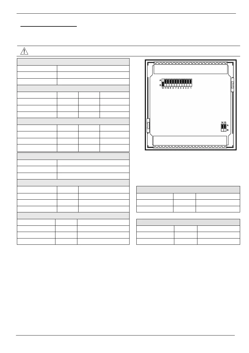
Input Jumper Settings
The tables below show how to set a specific jumper to change input functionality. To access the I/O
jumpers, you must open the controller according to the instructions beginning on page 13.
Incompatible jumper settings and wiring connections may seriously damage the controller.
Digital Inputs 0-11: Set Type
Set to JP12 (all Inputs)
npn (sink) A
pnp (source)* B
Inputs 7/8: Set Type - Digital or RTD/TC #1
Set to JP1 JP2 JP3
Digital* A A A
Thermocouple B B B
PT100 B A B
Inputs 9/10: Set Type - Digital or RTD/TC #0
Set to JP5 JP6 JP7
Digital* A A A
Thermocouple B B B
PT100 B A B
Input 11: Set Type - Digital or CM for PT100
Set to JP11
Digital* A
CM for PT100 B
Input 5: Set Type - Digital or Analog #3
Set to JP4 JP10
Analog Output 0: Set to Voltage/Current
Digital* A A
Set to JP13
Voltage B A Voltage* A
Current B B Current B
Input 6: Set Type - Digital or Analog #2
Set to JP8 JP9
Analog Output 1: Set to Voltage/Current
Digital* A A
Set to JP14
Voltage B A Voltage* A
Current B B
Current B
*Default settings