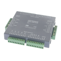
3/05 V200-18-E5B Snap-in I/O Module
Unitronics 9
V200-18-E5B Technical Specifications
Digital Inputs
Number of inputs 18 (in two groups)
Input type pnp (source) or npn (sink)
Galvanic isolation
Digital inputs to bus Yes
Digital inputs to digital inputs in
same group
No
Group to group, digital inputs Yes
Nominal input voltage 24VDC
Input voltage
pnp (source)
0-5VDC for Logic ‘0’
17-28.8VDC for Logic ‘1’
npn (sink)
17-28.8VDC for Logic ‘0’
0-5VDC for Logic ‘1’
Input current 8.8mA@24VDC for inputs #0 to #3
6mA@24VDC for inputs #4 to #17
Response time 10mSec typical for outputs #0 to #3
2mSec typical for outputs #4 to #17
High speed inputs Specifications below apply when these inputs are wired for use as a
high-speed counter input/shaft encoder. See Notes 1 and 2.
Resolution
32-bit
Frequency
10kHz maximum
Minimum pulse width
40µs
Notes:
1. Inputs #0 and #2 can each function as either high-speed counter or as part of a shaft encoder.
In each case, high-speed input specifications apply. When used as a normal digital input,
normal input specifications apply.
2. Inputs #1 and #3 can each function as either counter reset, or as a normal digital input; in
either case, its specifications are those of a normal digital input. These inputs may also be
used as part of a shaft encoder. In this case, high-speed input specifications apply.
Digital Outputs
Digital Output’s Power Supply
See Note 3.
Nominal operating voltage 24VDC
Operating voltage 20.4 to 28.8VDC
Quiescent current 20mA@24VDC.
Max. current consumption 80mA@24VDC. See Note 4.
Galvanic isolation
Digital power supply to bus Yes
Digital power supply to
transistor outputs
No
Notes:
3. V0 provides the power supply for Outputs #0, 1, 2, 3, 4, 5, 6, 7 and 8.
V1 provides the power supply for Outputs #9, 10, 11,12, 13, 14, 15 and 16.
V0 and V1 share a common 0V signal.
4. Maximum current consumption does not provide for pnp output requirements.
The additional current requirement of pnp outputs must be added.
i4 Automation Ltd - 01480 395256
 Loading...