V130/V350/V130J/V350J/V430J-TR34 models comprise a total of 22 inputs and 8 relay, 4 npn
outputs.
V130/V350/V130J/V350J/V430J-R34 models comprise a total of 22 inputs and 12 relay outputs.
Input functionality can be adapted as follows:
22 inputs may be used as digital inputs. They may be wired, in a group, and set to either
npn or pnp via a single jumper.
In addition, according to jumper settings and appropriate wiring:
- Inputs 14 and 15 can function as either digital or analog inputs.
- Inputs 0, 2, and 4 can function as high-speed counters, as part of a shaft-encoder,
or as normal digital inputs.
- Inputs 1, 3, and 5 can function as either counter reset, as part of a shaft-encoder,
or as normal digital inputs.
- If inputs 0, 2 and 4 are set as high-speed counters (without reset), inputs 1, 3 and 5
can function as normal digital inputs.
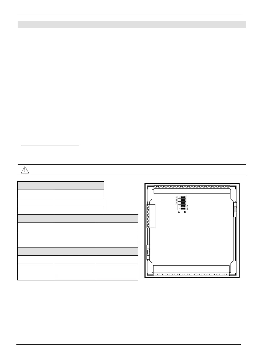
The tables below show how to set a specific jumper to change input functionality. To access the I/O
jumpers, you must open the controller according to the instructions beginning on page 12.