9. ROTOR.Klean – Semi Automatic Washing System
Installation
- Rotor Aeembly:
- See previous procedure
(Automatic Washing)
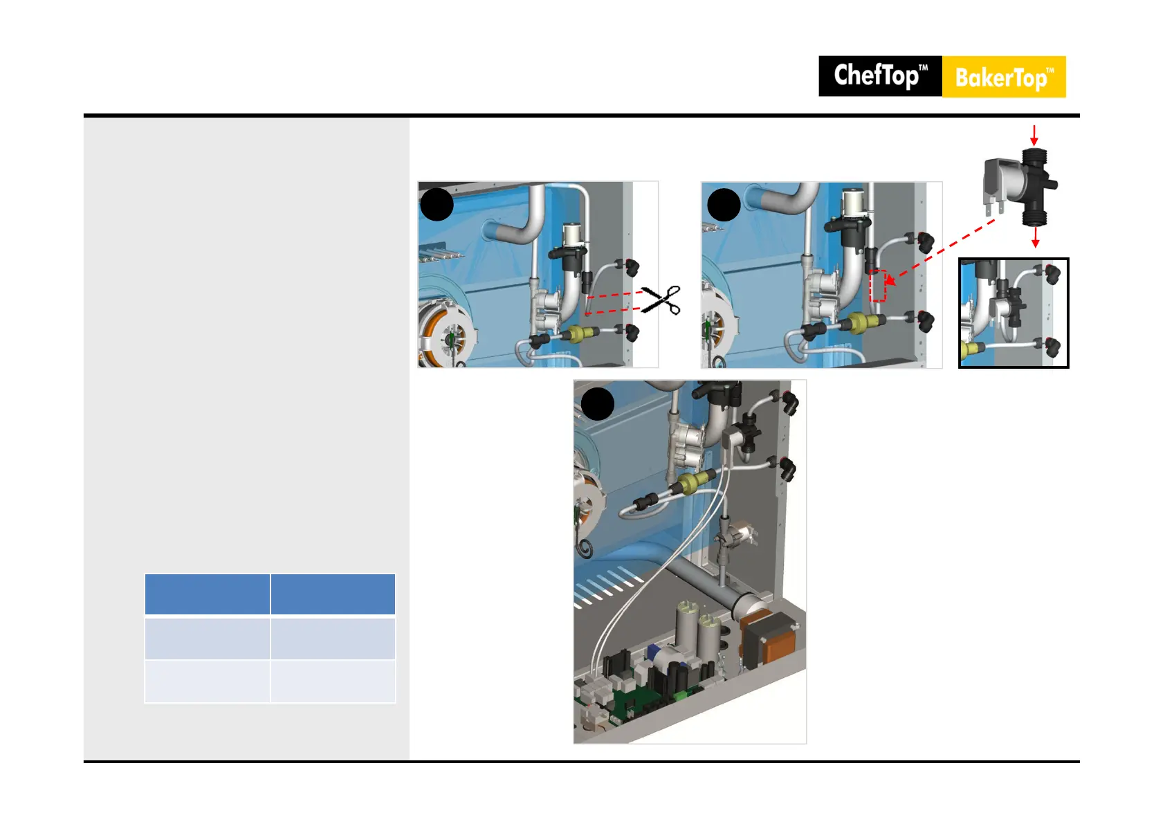
- Solenoid valve installation:
- Provide a cut of Ø 8 mm on
the washing system tube(after the
connector Washing In) (Picture B1).
- Connect the cables (supplied with
the kit) from the solenoid valve
connectors to the connectors on
the power board of the oven (9 pin
connector) or on the holding
cabinet (connector Inar Lock “P4”
of 3 pins) (Picture B3).
Solenoid valve installation
34
A
IN
OUT
C
B
EQUIPMENT
POWER BOARD
CONNECTOR
Oven
XVC-XBC
9 pin connector
Holding Cabinet
XVL
Inar Lock “P4” –
3 poli
 Loading...