56
12. CONTROL PANEL
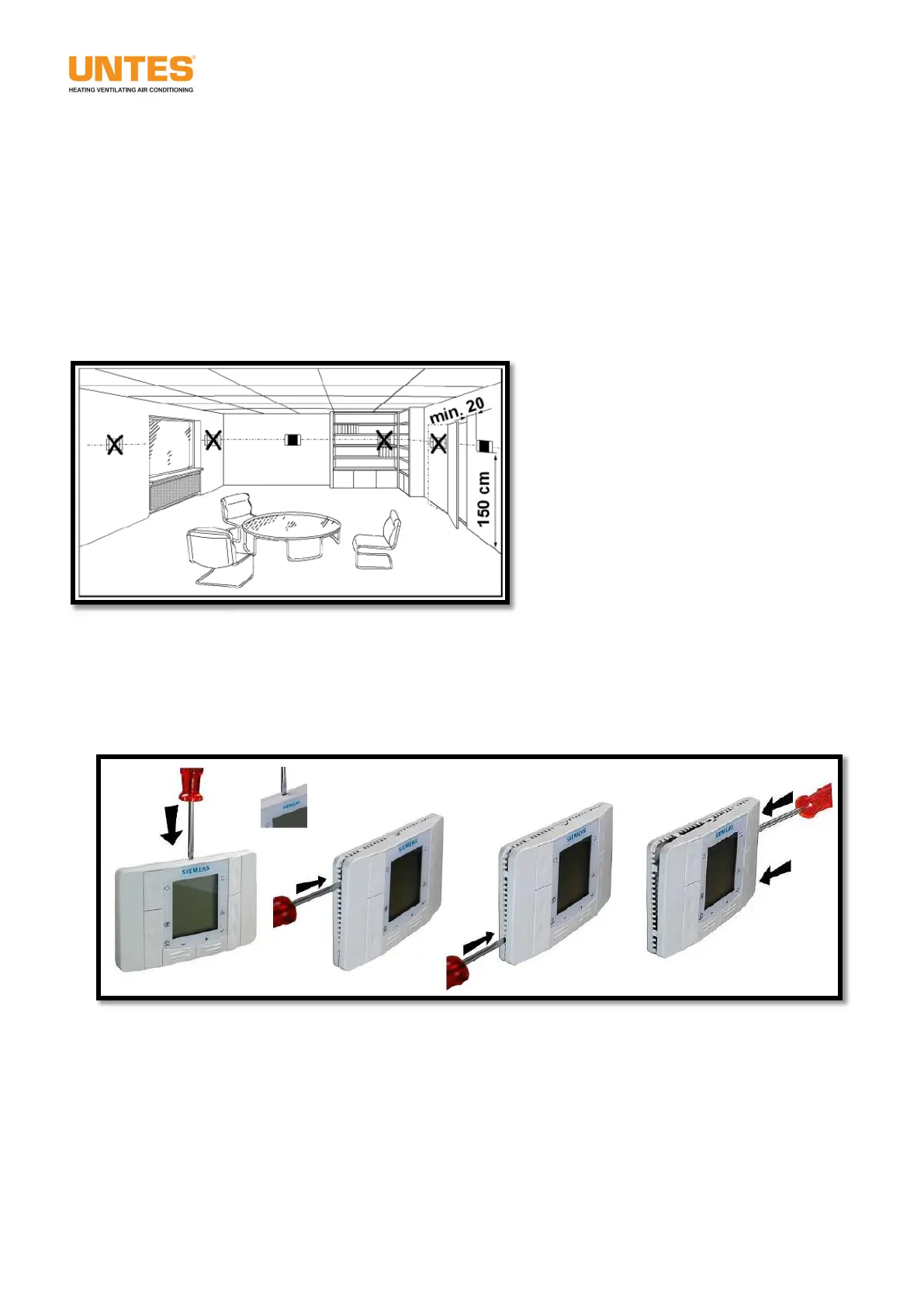
12.1. Installing and Using the Auto control Unit
It should be applied at a 1.5-meter height of a flat wall where the device can get the temperature of the
environment addressed properly, is not directly affected by the sunlight other heating/cooling sources and in
the following ways. The proper cable (2x 0,8mm
2
double-helix knx communication cable, twisted pair,
unscreened) should be extended by the customer between the "URTP" device and the room control unit. The
electrical cable connections should be made in compliance with the "URTP" device’s electrical project.
You can see in the following figures the demounting of the screening side and the back cover of the room
control unit, mounting of the back cover onto the wall and the points of the electrical cable connections
(CE+, CE-). You can find the detailed information from the documentation coming out of the box of the
room control unit.
 Loading...