4 | uponorpro.com
Installation
Preparation
Tools required
• Jeweller screwdriver
• Phillips head screwdriver
• Needle-nose pliers
• Wire stripper
Materials required
• 18 AWG LVT solid wire
(low-voltage connections)
• 24 VAC transformer
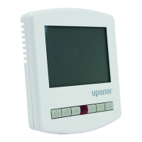
Physical dimensions
Installation location
When choosing the location for
the control, consider the following:
• Interior wall
• Keep dry; avoid potential leakage onto
the control
• Relative humidity less than 90%;
non-condensing environment
• No exposure to temperatures below -4ºF
(-20ºC) or above 122ºF (50ºC)
• No draft, direct sun or other cause for
inaccurate temperature readings
• Away from equipment, appliances or other
sources of electrical interference
• Easy access for wiring, viewing
and adjusting the display screen
• Maximum wire length of 500 feet (150m)
• Approximately 5 feet (1.5m) off the
nished oor
• Strip wire to ⅜" (10mm) for all terminal
connections
• Use standard 8-conductor, 18 AWG wire
Rough-in wiring
Low-voltage wiring
Pull each cable from the equipment to the
control’s plastic enclosure. All low-voltage
wiring connections enter the enclosure
through the square knockout on the rear.
Uponor recommends labeling each cable
for easy identication. Strip all low-voltage
wires to a length of ⅜" (9mm) to ensure
proper connection to the control.