* The thermostat can only be registered as a system device to a
Base PRO system with multiple controllers, if it is registered to
the master controller.
** Closed = ECO
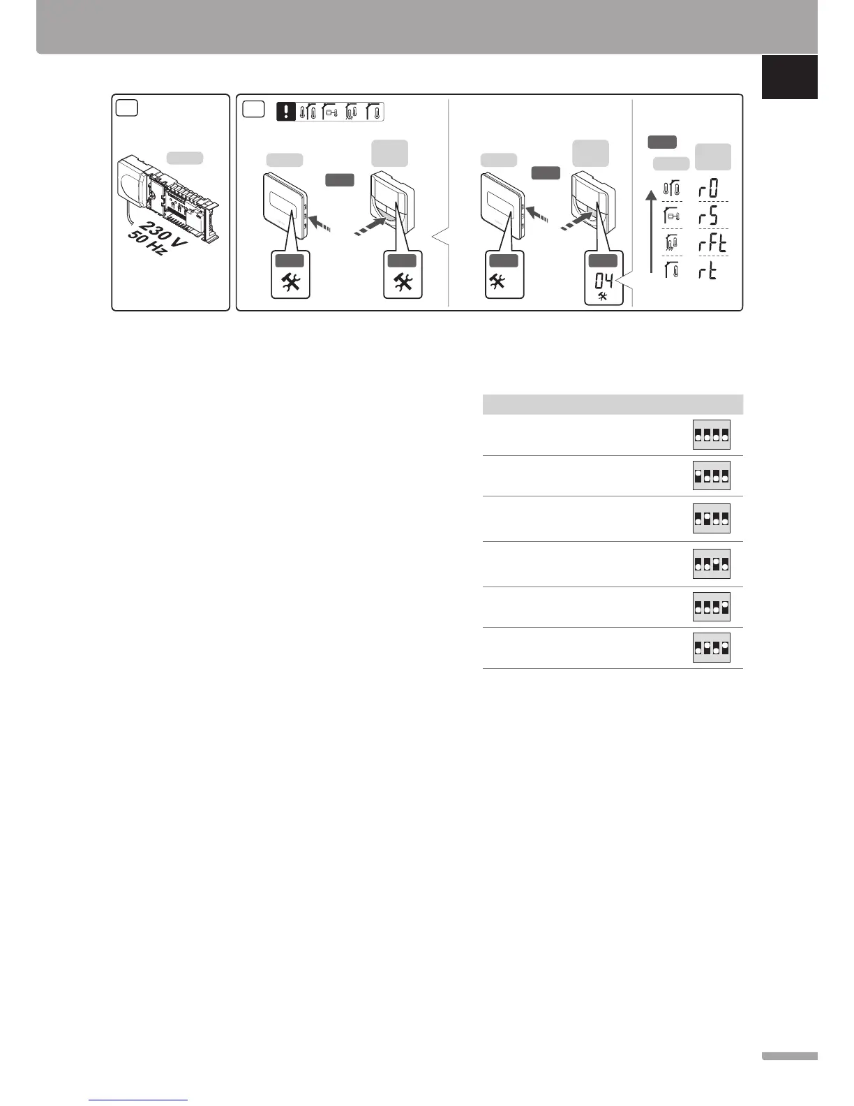
10. Connect the power cable to a 230 V AC wall socket,
or if required by local regulations, to a junction box.
11. Select thermostat control mode (settings menu 04,
in digital thermostats only). Default: RT (standard
room thermostat).
Register thermostats, the interface and other system
devices, in that order (next page).
Quick Guide
Installation
1. Attach the full assembly, or parts of it, to the wall
either with a DIN rail or by using wall screws and
plugs.
2. Connect the actuators.
3. Connect a thermostat communication cable to
the controller, slave module, and/or the optional
star module. Note: Daisy chain bus topology
is recommended. See page 8, Communications
protocol for more information.
4. Connect a thermostat communication cable to the
thermostat/timer.
5. Connect a system bus communication cable
in between controllers and route one cable to
the interface. Note: Daisy chain bus topology
is recommended. See page 8, Communications
protocol for more information.
6. Connect a system bus communication cable (7.1)
and a power cable (7.2) to the interface.
7. Check that all wiring is complete and correct:
• Actuators
• Heating/cooling switch
• Circulation pump
8. Ensure that the 230 V AC compartment of the
controller is closed and the fixing screw is tightened.
X-147
10
11
3 s
3 s
T-148
T-146
T-149
11.1
11.2
T-148
T-146
T-149
11.3
11.4
T-148
T-146
T-149
11.5
11.2 11.4
04