SL26/30SL Work Platform 3-17
M
AINTENANCE
Section
3.14
Disassembly
1. Unscrew the head cap from the cylinder barrel.
2. Remove the piston and rod assembly from the
cylinder barrel.
3. Unscrew the piston nut and remove piston and
head cap from the piston rod.
4. Remove the piston static O-ring from the cylinder
rod and discard.
5. Remove the piston seal from the piston and dis-
card.
6. Remove the static O-ring, rod seal and rod wiper.
7. Remove the rod end breather.
8. Do not remove the velocity fuse unless replace-
ment is necessary.
Cleaning and Inspection
1. Clean all the metal parts in cleaning solvent and
blow dry with filtered compressed air.
2. Check the working surfaces of the piston head
cap, cylinder barrel and rod for excessive wear or
scoring.
3. Replace parts found to be unserviceable.
4. Replace all seals, O-rings and wipers.
Reassembly
1. Lubricate the static O-ring, rod seal and rod wiper
and then install in the head cap.
2. Install the piston seal on the piston.
3. Install the head cap, piston static seal, piston and
piston nut on the cylinder rod. Torque nut to 96
Nm (70 ft. lbs.).
Note: The head cap should be installed from the
piston end of the cylinder rod. Sliding the head
cap over the pivot pin hole may damage the rod
seal and rod wiper.
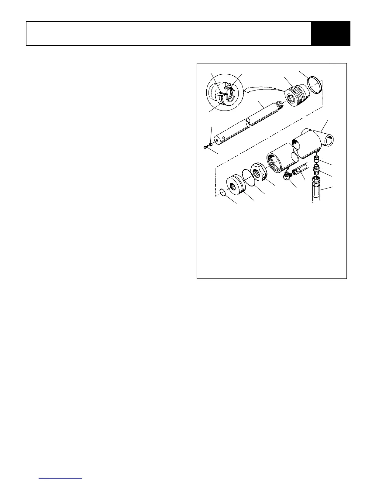
Figure 3-18: Lift Cylinder Assembly
4. Lubricate and piston seal and install the piston
and rod assembly into the cylinder barrel.
5. Screw the head cap into the cylinder barrel hand
tight and then turn 1/4 turn further.
Installation
Note: Before installing the cylinder, check the
pins and bearings for excessive wear. Replace
if necessary.
1. Place the cylinder in position taking care to sup-
port the cylinder to prevent falling.
2. Install the lower pin and retaining bolt.
3. Install the upper pin and retaining ring.
4. Install both hoses.
5. Raise the machine and check for leaks.
1. Cylinder Barrel
2. Velocity Fuse
3. Fitting, Adapter
4. Hose Assembly
5. Breather
6. Piston Nut
7. Piston Seal
8. Piston
9. Piston Static O-ring
10. Static O-ring
11. Head Cap
12. Cylinder Rod
13. Set Screw
14. Rod Wiper
15. Rod Seal
16. Nut
17. Hose Assembly
15
1
2
3
4
5
6
7
8
9
10
11
12
13
14
16
17
10
 Loading...