21
In some cases, such as driving the input of an engine control ECU, the 0-12 Volt
square wave signal will not be able to properly drive the device that it is
connected to. This is because some devices are only designed to accept an
input signal from a variable reluctance (magnetic coil) sensor. Because of this,
they may expect the input signal to swing below ground (0 Volts). To drive this
type of input, use the 5 Volt AC signal mode. In this mode, the driven device will
see a -2.5V to +2.5V signal.
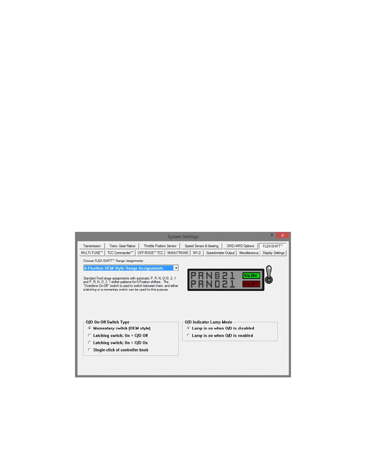
Overdrive On-Off Switch
The Overdrive switch can be used to turn overdrive on or off. The switch can be
a latching switch (toggle switch, latching push-button, etc.) or a momentary type
switch (spring-loaded push-button switch, spring-loaded toggle switch, etc.)
connected to +12v ignition-switched power and pin 4 (brown) of the vehicle
harness. (The tan wire on pin 12 is for VSS output and shouldn’t be confused
with the brown wire on pin 4 for the O/D switch.) A momentary switch is needed
to use more than 2 states. Optionally, you can add an O/D indicator lamp
between +12v ignition-switched power and pin 2 (white) of the vehicle harness.
This lamp will normally light up when overdrive is off. Also, without adding a
switch, a single-click of the controller’s knob can turn overdrive on and off. This
setting can be configured under the “Flex-Shift” tab of the tuning software.
Whenever the O/D or manual state is changed, it will be reflected in a change of
the PRNDL indicator on the home screen display (e.g. PRNO21 will change to
PRND21 or PRN321).
The FLEX-SHIFT Settings window. O/D settings are at the bottom.