8
Step 5: Final Connections
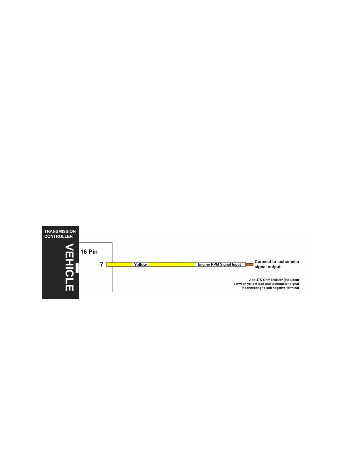
Engine RPM Signal Input
Connect the yellow lead (pin 7) from the vehicle harness to your tachometer
signal output. This is required for the learning procedure to work. The engine
RPM input can be connected to a digital tachometer output from an engine
computer or the tachometer output from an MSD ignition or similar CDI
(Capacitive Discharge Ignition) system, but NEVER to the coil outputs of a CDI
system like MSD.
For breaker points (or conventional electronic ignition systems such as GM HEI,
Ford Duraspark or TFI), it can be connected to the coil negative terminal. For
this configuration, add the supplied 47K Ohm resistor (yellow, violet, orange,
and gold bands) to the yellow lead (pin 7) in-line with the tachometer signal. The
correct setting will need to be set in the tuning software under Settings>Speed
Sensor & Gearing.
For COP (Coil on Plug) ignition systems that do not have a conventional
tachometer output (such as later Mustang engines), one of the coil trigger wires
can be used, but the update rate will be slow. A better approach for such
applications would be to use a tachometer adapter such as the AutoMeter 9117.
DO NOT run the engine RPM signal wire in the same wiring harness as the
speed sensor as this can cause interference.
Optional Features
Connect any extra features you wish to use. See the "Optional Features"
section on page 18 for details.