IM 50.560CA UA (B/4-03)
DEPOLOX
®
3 PLUS RESIDUAL ANALYZER
56
The interface works with differential voltage signals, ensuring high inter-
ference susceptibility.
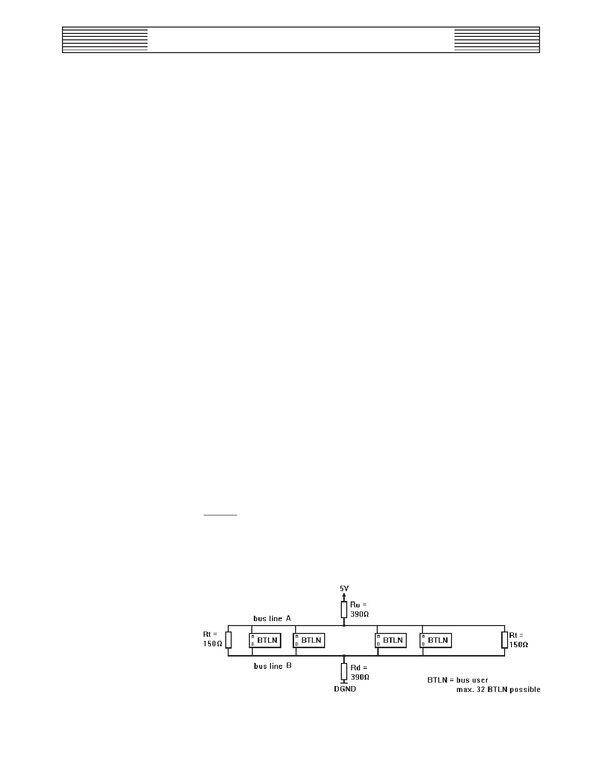
The bus system consists of a maximum of 32 passive users and one active
user. Only the active user (computer system) is entitled to start commu-
nication. The DEPOLOX 3 plus is always a passive user.
3.7.2.1 Cable
A shielded and twisted two-wire cable (twisted pair) is to be used. The
shield improves the electromagnetic compatibility. An unshielded cable
can be used if acceptable within the surroundings, that means, if no elec-
tromagnetic interferences are expected.
The bus cable is connected from one user to the next. Stub cables of a
maximum length of 0.3 m are allowed. The surge impedance of the cable
should be between 100 and 130 ohm, the cable capacitance preferably <60
pF/m and the cross section 0.22 mm² (e.g., Li2CY(TP) 2x0.22 mm²). If
using a shielded cable we recommend to connect the shield on both sides
with low resistance (large cross sections and short cables) to protection
ground, to have optimum interference compatibility.
3.7.2.2 Interface Connection
The bus cable for the communication with the DEPOLOX 3 plus should
be connected to the following terminals:
Bus line A: Terminal 28
Bus line B: Terminal 27
NOTE: The RS485 interface of the DEPOLOX 3 plus is not galvani-
cally isolated. Each DEPOLOX 3 plus occupies two bus addresses of
its own (e.g., 0 for chlorine, 1 for pH or for fluoride). This means that
in a bus system with DEPOLOX 3 plus-modules, each of the modules
behaves as two separate bus users.
Figure 3.7 - Interface Connection