IM 50.560CA UA (B/4-03) 11
DEPOLOX
®
3 PLUS RESIDUAL ANALYZER
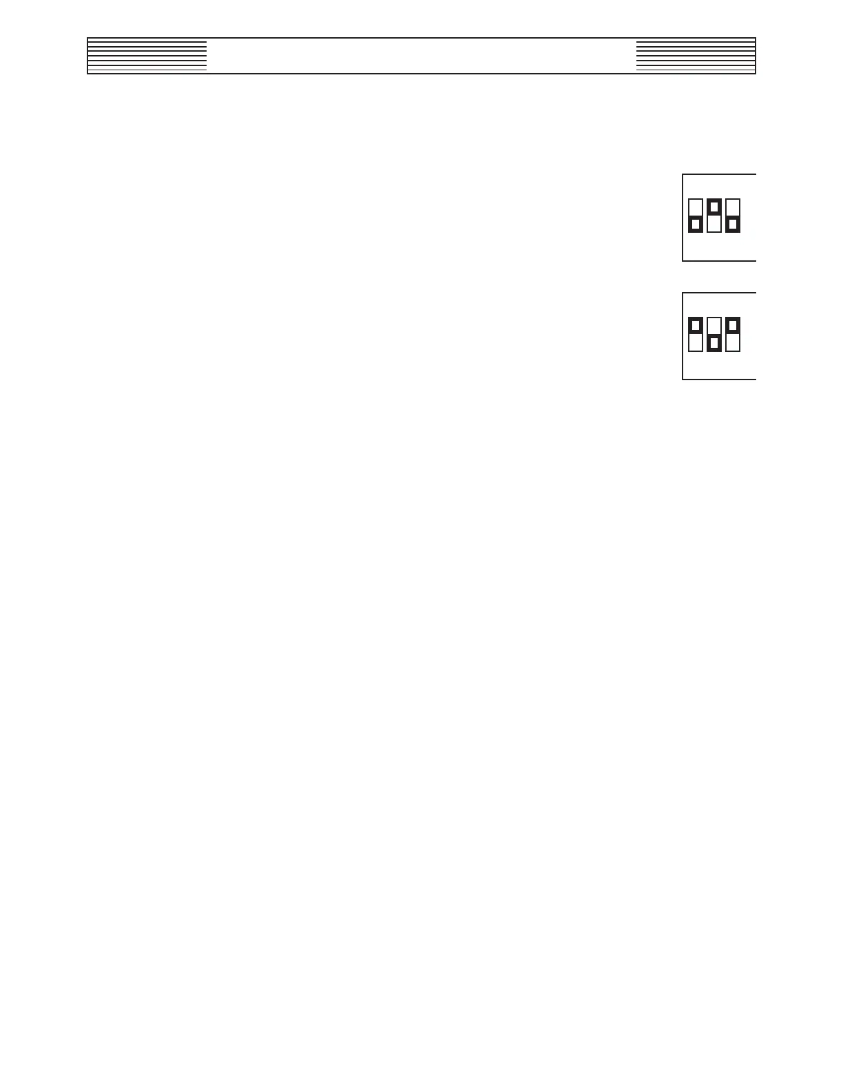
In case the cell current is >200µA (e.g., in waters with high conductivity),
change the setting of positions 1 through 3 as follows:
DIP Switch (default 200µA):
DIP Switch
(only if sensor current >200µA to max. 1000 µA):
The other positions remain as before.
2.1.5 Installing the DEPOLOX 3 plus Electronics Module
The DEPOLOX 3 plus electronics module is built in a wall-mounted
housing and should be mounted near the flow-through assembly.
2.1.6 Electrical Connections
Connect the sensor cables, alarm signal lines and the power cable accord-
ing to the wiring diagrams (see Dwgs. 50.560.155.010, .020, .030, .040,
and .050).
Do not switch on the power.
2.1.7 Digital Input
The flow switch (optional) must be connected to the terminals 25 and 26.
The digital input “Digital IN” is set for a potentially isolated external
contact, e.g., for the flow switch.
If the flow switch is not used, jumper terminals 25 and 26. Otherwise,
“Digital IN” error will occur.
123
OFF
123
OFF