7
EN
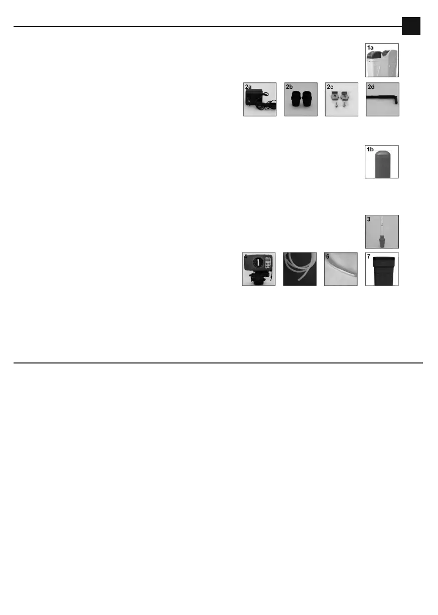
1. Component parts
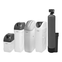
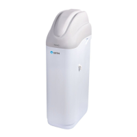
1.1 The compact device
1.2 The two-element device
1a. The assembled compact soener
2. Bypass along with accessories:
2a. Power supply
2b. Connections 1"
2c. Fasteners (for connecting the bypass with the head)
2d. Allen key
- The head operating instructions
- The device operating instructions
1b. A pressure vessel 10x54
2. Bypass along with accessories:
2a. Power supply
2b. Connections 1"
2c. Fasteners (for connecting the bypass with the head)
2d. Allen key
3. The distribution pipe with a lower basket (placed inside the vessel)
4. BNT165 head with the upper basket
5. 3/8" brine line (for connecting the brine tank to the control head injector)
6. Overflow line (to the outflow to the sewage system)
7. The complete brine tank with a float mounted inside and a flow tube
8. Bedding material
9. The ion-exchange (orange) material
10. Salt (optionally)
- The head operating instructions
- The device operating instructions
ATTENTION! Vessels 10x54 are not backfilled with the ion-exchange material, they must be filled by
the user.
ATTENTION! Move the feed valve to the off position and release the water supply network pressure.
Installation
2. Installation
The compact device should be connected towater installation in accordance with the diagram presented below, it is
recommended to install a sedimentation pre-filter before every device in order to protect the control head against the
potential mechanical impurities which can be present in the feed water.
The compact device assembly
1. Install the By-pass by means of fasteners (Fig.1)
2. Included connections 1" (2.2) connect to the installation (aer the water meter and/or hydrophore)
3. Connect the compact to connectors
4. Connect the exit hose (not included in the set)
5. Connect the overflow hose (not included in the set) In the case of mounting the overflow to the sewage system, an
air gap or, if there is no such a possibi-lity, a washing machine trap must be applied.